Introduction
RISC-V Embedded Systems Training
VEGA edition
Overview
This training is provided by RISC-V Ottawa, as a hands-on introduction to embedded systems development on RISC-V, built around the OpenISA VEGAboard. Across the sessions, you’ll set up a modern containerized toolchain, write and debug firmware for a real RISC-V microcontroller, simulate the same hardware purely in software using Renode, and finally learn how to run applications on top of the Zephyr RTOS.

No prior embedded or RISC-V experience is assumed, though comfort with C and the command line will help.
What will you learn?
The goal of this training material is to teach you the following:
- How to setup a modern containerized embedded systems development environment
- The basics of RISC-V firmware development
- Focus will be on the OpenISA VEGAboard (RV32M1-VEGA) development board
- Simulating hardware using Renode
- The basics of real-time operating systems (RTOS) and Zephyr
In the end, the hope is that you gain fundamental generalizable knowledge relating to the development of firmware for microcontroller-based systems.
Why RISC-V?
RISC-V is an open, royalty-free Instruction Set Architecture (ISA) originally developed at UC Berkeley in 2010. Unlike ARM or x86, anyone can implement a RISC-V processor without licensing fees or legal agreements, and anyone can read the official specification without signing an NDA.
That openness has turned RISC-V into something much larger than a research or education project. It has crept into virtually every corner of industry. NVIDIA alone ships over a billion RISC-V cores embedded throughout its hardware stack, a number that sounds absurd until you see how pervasively they use it across GPUs, embedded controllers, and security subsystems. If you use a modern SSD, GPU, or cloud service, you may be running RISC-V without even knowing it.
The ecosystem that has grown around the specification is what makes RISC-V more than just another ISA. RISC-V International, the non-profit Swiss foundation that governs the standard, coordinates hundreds of member organizations, from chip vendors and hyperscalers to universities and independent engineers, all of whom have an equal seat at the table. The specification itself evolves in the open on public mailing lists and GitHub repositories, in contrast to the closed processes behind proprietary ISAs.
Around that core specification, a layer of open-source silicon has emerged. The OpenHW Group develops production-quality, verification-heavy RISC-V cores (the CV32E40P and CVA6 families among them) that companies can integrate into real products. lowRISC, a non-profit based in Cambridge, maintains Ibex, a small 32-bit core that has found its way into everything from educational FPGA boards to the security subsystems of large-scale infrastructure. These are not toy designs; they are built, tested, and shipped in production hardware (for example, in Google Chromebooks).
The security research community has also adopted RISC-V as its testbed of choice, precisely because the ISA is hackable in the best sense: you can modify it, extend it, and tape out your ideas. The RISC-V Platform Security Model Specification is a framework for hardware-level security primitives, covering physical memory protection, trusted execution environments, and attestation. At the research frontier, CHERI (Capability Hardware Enhanced RISC Instructions), and specifically CHERIoT (its adaptation for microcontrollers), is implemented as a RISC-V extension. CHERIoT runs on real hardware today, including on the Sonata FPGA board, which is built around the Ibex core. That same Ibex core powers Google’s OpenTitan root-of-trust chip.
So when you learn RISC-V, you are not learning a niche curiosity. The ISA we will be using in this training relates to research, silicon that ships in billions of devices, and secures real systems.
At a high-level, RISC-V is:
- Open: a royalty-free Instruction Set Architecture (ISA) originally developed at UC Berkeley in 2010 and now governed by an open and transparent non-profit foundation (RISC-V International).
- Community driven: primarily driven and evolved through open-source specifications and implementations, allowing individuals (like us) and industry to freely contribute and continually advance it.
- Modular: The RV32I for 32-bit and RV64I for 64-bit base instruction sets are the minimum for each implementation (our development board builds on RV32I, adding the M and C extensions, i.e. RV32IMC). After that, there are over 100 ratified extensions to pick and choose from when designing real-world hardware.
Note
You may be thinking that writing software for an architecture supporting 100+ extensions would be a comparative nightmare. To avoid such nightmares, RISC-V has developed something called profiles which “are named groupings of standard processor ISA bases plus extensions (each identified as Mandatory or Optional)”.
RISC-V was shaped by decades of lessons from earlier architectures (MIPS, SPARC, Alpha, ARM), and its designers made deliberate choices that directly affect how simple our hardware implementation can be. The RISC-V Reader summarizes this beautifully in its very first chapter by considering many aspects important to ISA design such as cost, simplicity, performance, isolation of architecture from implementation, room for growth, program size, and ease of programming. If you want to learn more about the RISC-V ISA on your own as we progress, it is highly recommended to pick up a copy of the RISC-V Reader!
All-in-all, RISC-V is here to stay, it is open, and growing fast. We hope this motivates you to learn and continue this training with us!
Development environment
Overview
Embedded development has a reputation for being fiddly to set up. You typically need a specific compiler (one that produces code for your microcontroller rather than your laptop), a program that talks to the debug probe on the board, a handful of supporting libraries, and sometimes a simulator. Getting all of the above installed correctly can sometimes become a nightmare! To avoid this, this training will use a containerized development environment.
Note
A container is a lightweight, isolated Linux environment that runs on top of your own operating system (your “host”). Similar to virtual machines, you can think of it as an isolated box that you can use to run and install custom software inside without affecting your host system.
We’ll provide a custom pre-built container image for this training that contains everything you’ll need.
The container image is described by a single Containerfile in the vega-quickstart repository. You will never need to read through or edit it by hand (but feel free to take a look to learn more).
The Visual Studio Code Dev Containers extension handles everything: when you open the vega-quickstart folder in Visual Studio Code, it pulls the container (the first time only, which takes a few minutes), starts it, makes your project folder visible inside it, and attaches the editor to a shell running in it. From your point of view, you are just editing files and using a terminal as usual; under the hood those actions are happening inside the container.
What is inside the container?
The container is built on Ubuntu 24.04 (a common Linux distribution). On top of that base, it includes three main pieces:
- Custom RISC-V compiler suite, often called a toolchain: the compiler, linker, and related tools that turn C source code into a binary the VEGAboard can execute. We use the prebuilt toolchain from OpenISA. The VEGAboard’s RI5CY core implements
rv32imc(the 32-bit integer base plus the multiply/divide and compressed extensions), and that’s what we compile for. - Renode, a simulator that can virtually emulate a VEGAboard. This lets you run and debug your firmware without any physical hardware attached, which is handy for getting started and for experimenting.
- OpenOCD, the program that communicates with the debug probe on the board. A debug probe is the small circuit, built into the VEGAboard, that lets your computer load firmware onto the chip and step through the running code.
Alongside the above, the image contains some additional utilities (make, git, vim, minicom, etc) and creates a regular, non-administrator user called dev that you will be logged in as when you open a terminal.
How VS Code ties it together
The devcontainer.json file under the .devcontainer directory tells VS Code how to launch the container. Two details are worth knowing about:
- The container is started in privileged mode so that USB devices on your host (importantly, the debug probe on the VEGAboard) are visible inside it
- VS Code automatically installs a small set of extensions inside the container for you: C/C++ tooling, Makefile support, CMake highlighting, GitLens, a spell checker, and XML/YAML helpers. You do not need to install any of these yourself.
- These extensions are also defined in
devcontainer.json, feel free to add additional extensions that you typically use
- These extensions are also defined in
Host requirements
Your host machine only needs four things:
- A container runtime - this is the program that actually runs containers
- Docker Desktop is the easiest choice on macOS and Windows
- On Linux you can use Docker Engine or Podman
- Visual Studio Code
- The Dev Containers extension for VS Code
- Git - the standard version control tool which you’ll use to pull down the quickstart template (see the next section)
Quickstart template
Once you’ve installed the above, clone the vega-quickstart repository to your machine:
git clone https://github.com/riscv-ottawa/vega-quickstart.git
Open the cloned repository folder in VS Code, and accept the prompt to “Reopen in Container”. After a few minutes, VS Code should drop you into a terminal inside the container. From there you can edit code, run make to build firmware, run Renode to simulate the board, or (if your host is set up for it) connect to the real VEGAboard over USB. When you are done, closing VS Code shuts the container down; any code changes stay on your host.
The rest of this page covers the host-specific setup that the container cannot handle on its own. Most of it is about giving the container permission to see the VEGAboard’s USB connection.
Additional host-specific help
Linux
Install Docker Engine (or Podman) and VS Code using your distribution’s package manager or the upstream instructions. It may be worth adding your user to the docker group so that VS Code can talk to the container runtime without asking for a password every time (see the official Docker post-installation steps for more info).
Finally, USB permissions will need one small tweak. If connecting to the physical VEGAboard, you’ll likely be using the Segger J-Link debug probe provided in the box.
This device identifies itself to your computer with USB vendor ID 1366. By default Linux only lets the root user open such devices, which is a problem because the container runs as the unprivileged dev user. The fix is a udev rule: a one-line configuration that tells the kernel to make the device readable and writable by everyone on the machine.
To create the udev rule, run the following commands:
sudo tee /etc/udev/rules.d/99-jlink.rules <<'EOF'
SUBSYSTEM=="usb", ATTR{idVendor}=="1366", MODE="0666"
EOF

sudo udevadm control --reload-rules
sudo udevadm trigger
Unplug and replug the VEGAboard after applying the rule. You should then be able to flash and debug from inside the container.
Note
USB device visibility inside containers can sometimes be finicky. If you run into issues connecting to your board:
- Double check the board is plugged in properly
- See if your host recognizes the device by running
lsusborls /dev/tty*- If the device is there on the host, but not in the container - try restarting the container with
docker restart <container-name>
Tip
If you are using Podman instead of Docker, make sure its socket is enabled (
systemctl --user enable --now podman.socket) and point the Dev Containers extension at it via thedev.containers.dockerPathsetting.
MacOS
Install Docker Desktop for Mac and VS Code. Grant it full disk access if it prompts you, otherwise it cannot share your project folder with the container.
There is one thing that the container cannot do on macOS: talk to the VEGAboard over USB. Docker Desktop’s internal VM does not expose your Mac’s USB ports, so the debug probe is invisible from inside the container. You can still do all editing, building, and simulation inside the container, exactly like on Linux and Windows. However, if you have a physical board and want to flash it, you will install the OpenISA SDK natively on macOS and run OpenOCD from there.
ARM-based
One additional exception for MacOS is if you’re using a newer Apple Silicon (M1 and newer) machine. Both the container image and the OpenISA macOS bundle are Intel (x86_64). Luckily, macOS can run them transparently through Apple’s Rosetta 2 translation layer.
Install it once with:
softwareupdate --install-rosetta --agree-to-license
Then open Docker Desktop’s settings and enable “Use Rosetta for x86/amd64 emulation on Apple Silicon” under General.
Note
Builds and simulations may be noticeably slower than on an Intel Mac or a native Linux machine due to emulation, but everything should still work.
Installing the OpenISA SDK (for flashing real hardware)
OpenISA publishes a macOS bundle that contains their prebuilt toolchain and a working OpenOCD. You only need this on macOS, and only for flashing.
-
From the open-isa.org v1.0.0 release, download these two files into a working directory of your choice (for example
~/rv32m1/):Toolchain_Mac.tar.gzrv32m1_sdk_riscv_installer.sh
-
Run the SDK installer from that same directory. It will unpack both the SDK and the toolchain/OpenOCD side by side:
cd ~/rv32m1 chmod +x rv32m1_sdk_riscv_installer.sh ./rv32m1_sdk_riscv_installer.sh -
Add OpenOCD to your shell’s
PATHso you can invoke it from any terminal. Adjust the path if the installer puts it somewhere different on your system:echo 'export PATH="$HOME/rv32m1/Toolchain_Mac/riscv32-unknown-elf-gcc/openocd/bin:$PATH"' >> ~/.zshrc source ~/.zshrc openocd --version
When you are ready to flash, open a native macOS terminal (not the one inside the container) in the same project folder and run the project’s flash target, or invoke openocd directly with the project’s .cfg. The container and the host share the folder, so the firmware you just built inside the container is already visible from your Mac terminal.
Windows
Install Docker Desktop for Windows with the WSL2 backend (this is the default in recent versions). WSL2, short for Windows Subsystem for Linux 2, is a lightweight Linux VM that Windows ships with; Docker Desktop uses it to run containers. You will also want VS Code and the Dev Containers extension installed on the Windows side. The extension launches the container inside the WSL2 VM and then connects to it.
For USB access to the VEGAboard, install usbipd-win, a small open-source tool that forwards USB devices from Windows into a WSL2 environment. After installing it, open an elevated PowerShell window and run:
usbipd list
usbipd bind --busid <BUSID>
usbipd attach --wsl --busid <BUSID>
Replace <BUSID> with the identifier shown for the J-Link device in the output of usbipd list (look for vendor ID 1366). You will need to re-run the attach command each time you unplug the board or reboot. Once attached, running lsusb inside the container should list the probe.
Firmware development
This section introduces the primary focus of this training: firmware development on RISC-V based microcontrollers.
The plan for this section:
- Wait, what is firmware? will cover the main concepts relating to firmware development in general.
- Blinky! covers writing our first firmware program to blink a single LED onboard the VEGAboard.
- Connecting to real hardware to flash and run our programs on a real physical VEGAboard.
- Simulating hardware to virtually simulate the VEGAboard and run your programs in simulation (directly on your laptop!).
- Challenge asks you to extend the blinky program to support all 3 colors of the onboard RGB LED.
Wait, what is firmware?
In our case, firmware is the software that will be running directly on our microcontroller.
Note
Wait, what is a microcontroller?
A microcontroller unit (MCU) is a whole tiny computer packed onto a single chip: a CPU, a small amount of memory (both flash for code and RAM for data), and a fixed set of peripherals, all sharing the same piece of silicon. The VEGAboard’s main chip, the RV32M1, is one example.
Different from the microprocessor in your laptop, which only handles the CPU part and relies on separate chips for RAM, storage, and I/O. Because an MCU has everything on-board (and typically has it in much smaller proportions), it can be small, cheap, and low-power enough to live inside a thermostat, a car’s door lock, a pair of headphones, etc - all of which run one (or a handful of) small dedicated fixed programs (i.e., the firmware).
Firmware is the code that lives in the chip’s flash memory, starts running the instant power is applied, and continues executing until power is removed (or the system crashes ;D). Unlike a desktop application, it sometimes has no operating system underneath it at all. It is simply a program that talks to hardware.
Because the hardware is so much smaller than a laptop (often a few hundred kilobytes of flash, tens of kilobytes of RAM, and a single CPU running in the tens of megahertz), firmware is written with those constraints in mind. At times, every byte of memory needs to be minimized, every clock cycle accounted for, and the program has to handle everything itself: setting up the chip after reset, reacting to signals from the outside world, and keeping track of time.
The sections below walk through the three ideas that set firmware apart from “regular” software: how a program starts when there is no operating system to launch it, how a single CPU juggles many things at once, and how the code actually interacts with the physical world around it.
How execution starts
On a desktop, your operating system loads your program into memory, sets up its stack, and calls main(). On a bare-metal microcontroller, there is no operating system to do any of that. The chip has to bring itself up from nothing.
When the VEGAboard powers on (or you press reset), the CPU begins executing from a fixed, known address in flash. Typically, the very first thing it finds there is the vector table: a small array of addresses that tell the CPU where to jump for important events, with the very first entry being the reset handler. The reset handler is just a function, usually written in a mix of assembly and C, and its job is to prepare the chip to run your code.
That preparation does a few things in order:
- Set up the stack pointer so the CPU has somewhere to store local variables and return addresses.
- Copy any initialized global variables (the
.datasection) from flash into RAM, since RAM starts out with undefined contents. - Zero out uninitialized globals (the
.bsssection), so variables declared without an initializer start at0. - Optionally configure the chip’s clocks, caches, and other essentials.
- Finally, call
main().
Only after all of the above does your main() function actually start running. And unlike on a desktop, main() on a microcontroller almost never returns. There is nothing for it to return to. Instead it typically ends with an infinite while (1) loop that does the real work forever (as you gain experience in this area, you’ll learn that busy looping forever is typically a bad idea and that’s where things like deep sleep and time-based scheduling comes in).
Note
If you want to see this process in full detail (for a different chip, but with the same ideas), Memfault’s Zero to main() series walks through every step of startup code, from the reset vector to the first line of
main.
What is a peripheral?
Doing random computation is great and all, but how can computation on something like the VEGAboard result in sensing or actuation in the real physical world?
A CPU on its own can add numbers and move data around in memory, but it cannot blink an LED, send a byte over a wire, or sample a voltage. Those jobs are handled by peripherals: dedicated hardware blocks that sit next to the CPU inside the microcontroller. Typical peripherals include GPIO (general-purpose I/O pins), UART (serial communication), SPI and I2C (for talking to external chips), timers, and ADCs (analog-to-digital converters).
One thing to note about peripherals is that they run independently of the CPU. Once you configure a UART peripheral and hand it a byte to transmit, it shifts the bits out on its own while the CPU goes off to do something else. In that sense, a microcontroller is really a small CPU surrounded by a dozen tiny, single-purpose coprocessors.
The way the CPU talks to these peripherals is called memory-mapped I/O. Each peripheral has a block of addresses reserved for it in the chip’s address space, and within that block sit a handful of registers, each controlling one aspect of the peripheral. Writing to an address directly changes a peripheral’s behaviour. Reading an address gives you a peripheral’s current state.
For example, the VEGAboard’s LED is connected to pin 24 of GPIO port A. The GPIOA peripheral lives at address 0x48020000 and exposes six 32-bit registers back-to-back in memory:
GPIOA @ 0x48020000

0x48020000  ┌───────────────────────────┐
            │ PDOR  (RW)                │  Output latch: 1 bit per pin.
0x48020004  ├───────────────────────────┤
            │ PSOR  (WO)                │  Write 1 to *set* PDOR bits.
0x48020008  ├───────────────────────────┤
            │ PCOR  (WO)                │  Write 1 to *clear* PDOR bits.
0x4802000C  ├───────────────────────────┤
            │ PTOR  (WO)                │  Write 1 to *toggle* PDOR bits.
0x48020010  ├───────────────────────────┤
            │ PDIR  (RO)                │  Reads back the actual pin state.
0x48020014  ├───────────────────────────┤
            │ PDDR  (RW)                │  Direction: 0 = input, 1 = output.
0x48020018  └───────────────────────────┘

("RW" = read+write, "WO" = write-only, "RO" = read-only)
Within a single register, each of the 32 bits maps to one pin on the port. For PDOR, bit 24 is the one wired to the LED:
PDOR @ 0x48020000
   bit 31        bit 24                                          bit 0
    │             │                                               │
    v             v                                               v
   ┌─┬─┬─┬─┬─┬─┬─┬─┬─┬─┬─┬─┬─┬─┬─┬─┬─┬─┬─┬─┬─┬─┬─┬─┬─┬─┬─┬─┬─┬─┬─┬─┐
   │ │ │ │ │ │ │ │L│ │ │ │ │ │ │ │ │ │ │ │ │ │ │ │ │ │ │ │ │ │ │ │ │
   └─┴─┴─┴─┴─┴─┴─┴─┴─┴─┴─┴─┴─┴─┴─┴─┴─┴─┴─┴─┴─┴─┴─┴─┴─┴─┴─┴─┴─┴─┴─┴─┘
                      L = LED (1 = on, 0 = off)
Setting bit 24 of PDOR turns the LED on; clearing it turns the LED off. In C, that looks roughly like:
volatile uint32_t *pdor = (uint32_t *)0x48020000;
*pdor |= (1 << 24);   // LED on
*pdor &= ~(1 << 24);  // LED off
You will rarely write code quite that raw in practice. Vendor-supplied software development kits (SDKs) wrap these registers in named structs and helper functions so you can write something like GPIO_PinWrite(GPIOA, 24, 1) instead. But underneath those abstractions, every peripheral interaction bottoms out in a load or store to a specific memory address.
How is multitasking done on MCUs?
Firmware will often do stuff like blink an LED, read a sensor, respond to a button, and print out data, all “at the same time”…how?
The simplest and most common pattern is a super loop: one big while (1) inside main that checks each task in turn and does a bit of work for each one. It looks something like this:
int main(void) {
    setup_everything();
    while (1) {
        update_led();
        read_sensor_if_ready();
        handle_uart();
    }
}
As long as none of the individual tasks block for too long, each one gets serviced often enough to feel simultaneous. The blinky application you’ll meet in the next section is the most minimal version of this pattern: a single while (1) that toggles a GPIO pin and waits.
The super loop breaks down when something needs to happen right now, for example, reacting the microsecond a pulse arrives on a pin. For that, microcontrollers provide interrupts: hardware signals that pause whatever the CPU is doing, jump to a small handler function to deal with the event, and then resume the interrupted code. We’ll dedicate a later section to interrupts and timers, but the short version is that well-designed firmware usually combines both: a super loop doing the slow, steady work, and interrupts handling anything that is time-sensitive.
When the super loop stops scaling (many independent tasks, strict timing deadlines, multiple developers working in parallel), the next step up is a real-time operating system, or RTOS. An RTOS lets you write each task as if it had the CPU to itself and takes care of switching between them. The RTOS section of this training covers this briefly by introducing Zephyr.
TLDR
- Firmware is the software that runs directly on a microcontroller (MCU), typically with no general purpose operating system beneath it and tight limits on memory and CPU speed.
- An MCU starts executing from a fixed address in flash. Startup code sets up the stack, initializes memory, and eventually calls
main(), which never returns. - Peripherals are small, independent hardware blocks (GPIO, UART, timers, etc) that the CPU drives by reading and writing specific memory addresses. Every firmware operation eventually boils down to a load or store instruction (defined in the RV32I spec!).
- A single CPU core fakes multitasking through a super loop plus interrupts. When applications become too complex, people typically use an RTOS for better abstraction and task handling.
Blinky!
The classic “hello world” of firmware is getting a single LED to blink. It sounds trivial, but under the hood it touches a surprising number of the ideas from the previous section: pin muxing, clock configuration, memory-mapped peripherals, and the super loop. This section walks through building and understanding the blinky application provided in the vega-quickstart repository.
Note
If you really want to have fun, it is recommended to download the RV32M1 reference manual and look through the related sections of the manual as you read through everything below.
The RV32M1 SDK
Blinking an LED by poking 0x48020000 directly (as we discussed in the previous section) works, but things will quickly get out of hand without better abstraction. As soon as you want a second GPIO, UART, timer, etc, you’re either re-reading the reference manual every session (it’s over 4000 pages!) or copy-pasting definitions across files. This is why chip vendors ship a software development kit (SDK): a collection of headers and drivers that wrap the raw peripheral registers in named structs and helper functions.
For the RV32M1, that SDK is the rv32m1-sdk.
The quickstart repository pulls this SDK in as a git submodule at vega-quickstart/rv32m1-sdk. If you cloned the quickstart without --recurse-submodules, the directory will be empty and every build will fail with “no such file” errors. To populate it, run the following from inside vega-quickstart:
git submodule update --init --recursive
Once populated, the layout underneath rv32m1-sdk/ looks roughly like this:
rv32m1-sdk/
├── devices/RV32M1/
│   ├── RV32M1_ri5cy.h               CMSIS-style definitions for every peripheral
│   ├── system_RV32M1_ri5cy.c        very early startup (SystemInit)
│   ├── gcc/startup_RV32M1_ri5cy.S   reset handler and vector table
│   ├── drivers/                     fsl_gpio, fsl_clock, fsl_lpuart, ...
│   └── utilities/                   debug console, printf, logging
├── boards/rv32m1_vega/              board-specific pin maps and vendor examples
├── RISCV/                           RISC-V specific intrinsics and CSR helpers
└── middleware/                      FreeRTOS, USB stack, etc (we ignore this)
Note
Fun fact: The
fsl_prefix on every driver file is a legacy remnant of Freescale Semiconductor, a company NXP acquired in 2015. It stands for “Freescale Software Library” and persists in here since NXP originally maintained this SDK.
Peeking inside a driver
Although not totally necessary for you to follow the rest of the training, let’s trace one call from the blinky application down to the bare-metal register write we saw last section. This will help you understand how to read and interact with the SDK source in the case that you want to develop your own applications in the future.
The application toggles the LED with:
GPIO_TogglePinsOutput(BOARD_LED_GPIO, 1u << BOARD_LED_GPIO_PIN);
BOARD_LED_GPIO is defined in the app’s own board.h as GPIOA, and BOARD_LED_GPIO_PIN is 24. The symbol GPIOA itself is defined deep in devices/RV32M1/RV32M1_ri5cy.h as:
#define GPIOA_BASE  (0x48020000u)
#define GPIOA       ((GPIO_Type *)GPIOA_BASE)
In English: GPIOA is just a pointer to a GPIO_Type struct laid out at address 0x48020000. The GPIO_Type struct is carefully declared so that its fields land exactly on top of the PDOR, PSOR, PCOR, PTOR, PDIR, and PDDR registers from the memory map (we looked at this in the previous section). Peek into drivers/fsl_gpio.h and the toggle helper is a single-line inline function:
static inline void GPIO_TogglePinsOutput(GPIO_Type *base, uint32_t mask) {
    base->PTOR = mask;
}
So GPIO_TogglePinsOutput(GPIOA, 1u << 24) compiles down to exactly the same store we wrote by hand in the previous section: a single 32-bit write of 0x01000000 to address 0x4802000C. The SDK is not doing anything magical here. It is giving us names for the same bits. The same pattern holds for GPIO_PinInit, GPIO_SetPinsOutput, and GPIO_ClearPinsOutput: each one is a thin wrapper over a single register access, and the compiler inlines and optimizes the function away.
Note
As we can see, an SDK is really just a readability layer, not a runtime.
Everything you write eventually comes down to a load or store instruction against a fixed address, and when something misbehaves you can (and should) open the driver source and read what it actually does.
Writing our first program
Our first application will be a small blinky program, you can find it under apps/blinky/ in the vega-quickstart repository:
apps/blinky/
├── board.h    pin and peripheral definitions
├── board.c    pin mux, clock, and UART setup
└── main.c     the main application logic and loop
board.c
Three functions are near the top of main.c, each of these come from board.c and are somewhat complex (relative to the rest of main.c).
BOARD_InitPins handles pin muxing. Physical pins on the RV32M1 package can be routed to several different peripherals: the same pin can act as GPIOA24, an analog input, or some set of other alternate functions. Selection is done by setting a handful of bits (the MUX bits) in the PORTA register block.
Note
You can find (a rather complicated) table of “pinouts” (definitions of all pin multiplexing options) in Section 23.3 of the reference manual.
Before we can drive the LED, we have to tell the chip that pin 24 of port A is a GPIO (as opposed of any of the other options). The function also enables the clock to PORTA and PORTC and routes PTC7 and PTC8 to LPUART0’s RX (receive) and TX (transmit) lines, since the debug console needs those pins.
BOARD_BootClockRUN configures the chip’s clock tree. Out of reset, the CPU is running from the internal Fast Frequency Internal Reference Clock (FIRC) oscillator.

For our simple blinky application, we don’t care that much about what speed the clock is running at. However, in most/all real applications you really must have clocks at a known speed and various peripheral dividers set up correctly; every peripheral, communication protocol, timer, and even the power utilized by the board relies on proper management and knowledge of clocks.
BOARD_InitDebugConsole points LPUART0’s clock source at the FIRC and hands the peripheral to the SDK’s debug console module at 115200 baud. Once this is done, any PRINTF() in the program will go out of pin PTC8 (LPUART0 TX) as serial data.
Note
“Baud” is the transmission/receiving rate of a serial interface in symbols per second. Because UART uses simple binary signaling where each symbol encodes exactly one bit, 115200 baud means 115200 bits per second (11520 bytes/characters per second) on the wire. A faster baud rate means faster communication between the two connected points.
Almost none of the code in board.c is what you would write from scratch for every project. You can usually just write it once per board and then mostly ignore, which is exactly what we’ve done here.
Note
The version in
apps/blinky/board.cis a trimmed-down adaptation of the vendor example atrv32m1-sdk/boards/rv32m1_vega/driver_examples/gpio/led_output/ri5cy/, rewritten to keep only what blinky actually uses.
main.c
#include "board.h"
#include "fsl_debug_console.h"
#include "fsl_gpio.h"

static void delay(void) {
    volatile uint32_t i;
    for (i = 0; i < 800000; ++i)
        __asm("NOP");
}

int main(void) {
    gpio_pin_config_t led_config = { kGPIO_DigitalOutput, 0 };

    BOARD_InitPins();
    BOARD_BootClockRUN();
    BOARD_InitDebugConsole();

    PRINTF("\r\nRV32M1-VEGA RI5CY baremetal app\r\n");

    GPIO_PinInit(BOARD_LED_GPIO, BOARD_LED_GPIO_PIN, &led_config);

    PRINTF("Starting to blink LED...\r\n");
    while (1) {
        delay();
        GPIO_TogglePinsOutput(BOARD_LED_GPIO, 1u << BOARD_LED_GPIO_PIN);
    }
}
Before entering the loop, main runs three board-level setup calls (imported via board.h), prints a banner over the UART, and configures pin 24 of GPIOA as a digital output with an initial value of 0 (LED off). After that it loops forever, waiting a bit and then toggling the LED.
A few things are worth calling out:
- The
delay()function is a busy loop, not a real timer (we’ll learn more about those in a later section)delay()blocks the CPU in a tightforwith an inlineNOP. The inlineNOPensures the compiler doesn’t optimize the loop away- The
volatilequalifier oniis for the same reason: without it, an optimizing compiler might notice that nothing depends oniand delete the whole loop - As we noted earlier, busy-looping is a bad long-term habit (it wastes power and blocks the CPU from doing anything useful), but for a first program it’s the easiest way to provide delays between our toggles
- The
PRINTFmacro is not theprintffrom the C standard library (since we don’t have a standard library for our bare-metal code). It expands to the SDK’s ownDbgConsole_Printf, which writes bytes out over LPUART0 one at a time- LPUART0 is connected to the J12 USB port on the physical VEGAboard, we’ll learn how to view the serial output in later sections
The flow of execution
Now that we’ve seen every piece, we can tie them together into the full path a single blink takes:
- Reset brings the CPU up running from the Fast Frequency Internal Reference Clock (FIRC), executes the startup assembly in
startup_RV32M1_ri5cy.S, zeroes.bss, copies.data, and callsmain. BOARD_InitPinswrites to PORTA and PORTC mux registers so pin 24 is GPIO and pins PTC7/PTC8 are LPUART0.BOARD_BootClockRUNsets the system clock to 48 MHz through using FIRC.BOARD_InitDebugConsoleprepares LPUART0 so that subsequentPRINTFcalls can emit characters.GPIO_PinInitwrites1 << 24into GPIOA’s PDDR register, marking that pin as an output.- The main super loop runs forever:
delay()burns a few hundred thousand NOPs worth of cycles, thenGPIO_TogglePinsOutputwrites0x01000000to GPIOA’s PTOR register, which flips bit 24 of PDOR in hardware, in turn toggling the LED.
Step 6 is the entirety of our application logic doing “useful work”. Everything else is just (largely generic) initial setup.
Compiling our program
Turning main.c into something that can run on the VEGAboard is a multi-stage process:
- Compile each
.cinto an object file with a cross-compiler - Assemble the startup code, link everything against a linker script that knows the chip’s memory layout
- Finally, convert the ELF output into a raw binary for flashing
Building manually
If you wanted to build everything entirely by hand (we don’t recommend it), the invocation would look something like this (shortened for readability):
# From vega-quickstart/
SDK=rv32m1-sdk
DEV=$SDK/devices/RV32M1
BOARD=$SDK/boards/rv32m1_vega

riscv32-unknown-elf-gcc -march=rv32imc -O0 -g -ffreestanding -fno-builtin \
    -DCPU_RV32M1_ri5cy -D__STARTUP_CLEAR_BSS \
    -I apps/blinky -I $DEV -I $DEV/drivers -I $DEV/utilities \
    -I $SDK/RISCV -I $SDK/devices \
    -c apps/blinky/main.c -o main.o
# ... repeat for board.c, system_RV32M1_ri5cy.c, fsl_gpio.c, fsl_clock.c,
#     fsl_msmc.c, fsl_lpuart.c, fsl_common.c, fsl_debug_console.c, etc.

riscv32-unknown-elf-gcc -march=rv32imc \
    -c $DEV/gcc/startup_RV32M1_ri5cy.S -o startup.o

riscv32-unknown-elf-gcc -march=rv32imc \
    -T $BOARD/driver_examples/gpio/led_output/ri5cy/riscvgcc/RV32M1_ri5cy_flash.ld \
    -ffreestanding -nostdlib -Xlinker --gc-sections \
    -Xlinker -z -Xlinker muldefs \
    -o blinky.elf main.o board.o startup.o ... \
    -Wl,--start-group -lm -lc -lgcc -lnosys -Wl,--end-group

riscv32-unknown-elf-objcopy -O binary blinky.elf blinky.bin
Note:
riscv32-unknown-elf-gccis a cross-compiler: it runs on your laptop but emits RISC-V instructions.- The
-march=rv32imcflag tells the compiler which subset of the RISC-V ISA to target: 32-bit base integer (i), multiply/divide (m), and compressed 16-bit encodings (c), which matches what the RI5CY core on the VEGA implements.
- The
-ffreestanding -fno-builtin -nostdlibtell GCC that no hosted C runtime exists. There is no operating system to provide memory allocators, a standard library, etc. The compiler must not assume that callingprintfcan reachstdout, and the linker must not pull in startup code from libc.- The linker script (
RV32M1_ri5cy_flash.ld) tells the linker where flash and RAM are located (in terms of memory addresses), which section goes where, and where the vector table has to be placed for the CPU to find it at reset.- Errors or incorrect addresses in the linker script may lead to immediate hard-faults the instant the board starts…such errors can be very hard to debug - try to use vendor-provided linker scripts whenever possible.
- The final
objcopycall strips the ELF formatting off the compiled code. The resulting.binis a flat dump of what the flash contents should look like.
Using the Makefile
Doing all of the above is not fun, especially since you need to do it every time you make changes and need to recompile. Thankfully, you don’t have to; the quickstart repository’s top-level Makefile wraps all of the above into a single command:
make blinky
The build output lands in build/blinky/:
build/blinky/
├── blinky.elf    full ELF with debug info
├── blinky.bin    flat binary
├── blinky.hex    Intel HEX
├── main.o
├── board.o
└── ... (all the other .o and .d files)
Note
At the end of a successful build the Makefile also runs
riscv32-unknown-elf-sizeon the ELF, printing thetext,data, andbsssizes. Those numbers are useful as a rough check of size. For example, our bare blinky app should just be a few kilobytes oftextat most. If you suddenly see it balloon in size, something you may not have intended may have snuck in.
The Makefile is organized so that adding a new application is just a matter of dropping a new directory under apps/ with one or more .c files inside. Running make <appname> builds it, make flash-<appname> builds and flashes it (covered in the real-hardware section next), and make sim-<appname> builds and runs it inside Renode (covered in simulating hardware section later). If a given application needs different compiler flags or extra SDK drivers, you can add an apps/<name>/config.mk file to override the relevant variables without touching the top-level build rules.
From here on out, no need to run compilation commands by hand, just use make! However, now when you make <app> and it prints a wall of compile lines and a final size breakdown, you know exactly what each of those lines is doing and why - awesome!
RISC-V aside: C extension
Now that we’ve compiled our first program, let’s take this as a chance to learn an interesting RISC-V specific detail.
If you take a look at the primary Makefile, you’ll notice we build every app with -march=rv32imc. The -march flag tells the compiler which RISC-V base ISA and extensions to target. In our case, it’s the 32-bit integer base (i), the multiply/divide extension (m), and the C extension (c) for compressed instructions, which lets the compiler emit 16-bit forms of common operations. Most of main will be 4-byte forms, but small moves and stack adjustments often can be shrunk to just 2 bytes when this extension is specified/supported.
You can see this by disassembling with GDB:
riscv32-unknown-elf-gdb -q -batch -ex 'disass /r main' build/blinky/blinky.elf
Look at the prologue of main. You’ll see lines like:
0x000003fa <+0>:  01 11           addi  sp,sp,-32     # 2-byte c.addi
0x000003fc <+2>:  06 ce           sw    ra,28(sp)     # 2-byte c.swsp
0x00000404 <+10>: 23 24 f4 fe     sw    a5,-24(s0)    # 4-byte sw
The instruction in the third column is the standard mnemonic; the raw bytes tell you the encoded length, two bytes for compressed forms and four for the full-width encoding. With the C extension, we get a bunch of small savings that together add up to a potentially significant decrease in binary size. A typical RV32IMC binary is roughly 20-30% smaller than the same code without c, which is why almost every microcontroller-class RISC-V chip enables it. We’ll come back to this in future sections, when we have to read trap-handler disassembly with both forms mixed together.
TLDR
- The RV32M1 SDK ships as a git submodule at
vega-quickstart/rv32m1-sdk. Populate it withgit submodule update --init --recursivebefore building. - SDK helpers like
GPIO_TogglePinsOutputare thin inlined wrappers over a single register store. They give the raw peripheral bits readable names without adding runtime cost. - The blinky app is one big super loop: initialize pins, clocks, and the UART; then forever delay and toggle GPIOA pin 24. All three init calls (
BOARD_InitPins,BOARD_BootClockRUN,BOARD_InitDebugConsole) are board scaffolding you write once and ignore thereafter. - Building for the VEGAboard uses the
riscv32-unknown-elf-cross-toolchain with-march=rv32imcand a vendor-supplied linker script, producing an.elfand.bin. The top-levelMakefilewraps all of this behindmake <app>. - The
-march=rv32imcflag selects the RISC-V base ISA and extensions:i(32-bit integer base),m(multiply/divide), andc(compressed instructions). The C extension lets the compiler emit 2-byte forms of common operations alongside the standard 4-byte ones, shrinking a typical binary by 20-30%.
Connecting to real hardware
With blinky built (recalling make blinky produces a blinky.elf and blinky.bin under build/blinky/), let’s try to actually get that binary onto the VEGAboard and watch it run. This section walks through the three things you’ll do every time you iterate on firmware: connect the board, flash your built binary, and, optionally, attach a debugger.
Connecting
There are 2 physical connections and a button that are important to us for running code on the VEGA. All of them are highlighted in the left image below; the right image shows what a connected setup looks like.

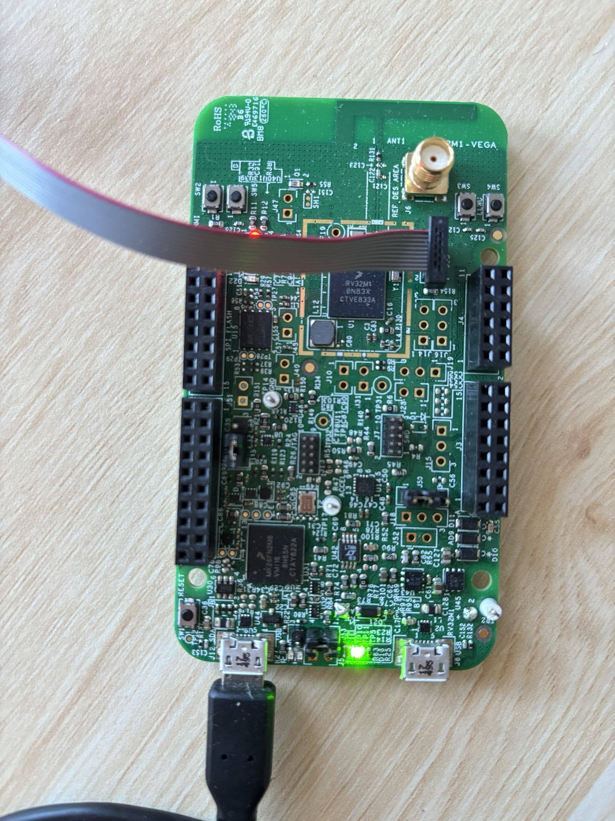
The OpenSDA USB port (J12) is a standard Micro-USB. Plugged into your laptop, it provides power to the board and also exposes LPUART0 (the pins we wired up in BOARD_InitDebugConsole) as a virtual serial device. On Linux (and inside our container) it usually enumerates as /dev/ttyACM0. This is the where you’ll see output from PRINTF() statements going to your terminal.
The RISC-V JTAG header (J55) is a small ribbon connector. The RV32M1 contains several CPU cores (RI5CY, ZERO-RISCY, and an ARM core) and this header is wired specifically to the JTAG chain of the RI5CY RISC-V core we care about. You can connect a SEGGER J-Link debugger here. Mind the ribbon cable orientation: the red stripe marks pin 1, and the right image above shows the correct direction. JTAG is the protocol every tool in the rest of this section uses to halt the CPU, program flash, set breakpoints, and single-step.
Note
Want to learn more about JTAG? See the Diving into JTAG series by Memfault.
The reset button (SW1) is a momentary push that pulls the chip’s reset line low. Pressing and releasing it re-runs the startup assembly from startup_RV32M1_ri5cy.S and re-enters main. Handy when a freshly-flashed image misbehaves, or when you just want a clean starting state without yanking the USB cable.
Flashing
“Flashing” means copying our built code into the non-volatile flash memory inside the RV32M1 so it persists across resets and power cycles. The binary data we send will travel out the J-Link over JTAG; for this, we use the Open On-Chip Debugger (OpenOCD) software (which translates JTAG data into higher-level “write this word to that address” operations) to talk to the chip’s on-board flash controller.
By hand
Flashing by hand looks like this:
openocd -f support/openocd/openocd_rv32m1_vega_ri5cy.cfg \
    -c "init" \
    -c "halt" \
    -c "ri5cy_boot" \
    -c "flash write_image erase build/blinky/blinky.elf" \
    -c "reset run" \
    -c "exit"
Each -c passes one TCL command to openocd after it finishes loading the config file:
initopens the JTAG connection and initializes openocd’s internal state.haltstops the CPU. We can’t reprogram the flash bank a program is currently executing from.ri5cy_bootis a vendor-supplied TCL routine defined in the config file. It selects the RI5CY core as the active target, since the chip exposes multiple cores on the same JTAG chain.flash write_image erase ...erases the sectors that will be written, then programs the ELF’s loadable segments into flash.reset runpulses reset and lets the CPU begin executing the newly-flashed image.exitdisconnects and shuts openocd down cleanly.
Note
If you are curious what
ri5cy_bootactually does, seesupport/openocd/openocd_rv32m1_vega_ri5cy.cfg. It essentially just pokes the chip’s control registers to bring the RI5CY core out of reset.
Using the Makefile
As always, the top-level Makefile provides a wrapper for easier use:
make flash-blinky
This first rebuilds the app if any source has changed, then hands the resulting ELF to openocd with the same command shown above. The command generalizes: make flash-<app> works for any app under apps/.
Debugging
Flashing gets code onto the board, but the moment something doesn’t work (wrong LED, hung in a loop, unexpected fault) you may need to inspect what the CPU is actually doing to get to the bottom of it. The same J-Link that programs flash can also act as a live window into the CPU’s state: we can halt the CPU at any address, read and write memory, inspect registers, and single-step through instructions.
The setup has two parts:
openocdruns as a GDB server, translating GDB’s remote serial protocol into JTAG operations. By convention, it listens on TCP port 3333.riscv32-unknown-elf-gdbruns as the client on your laptop. It loads the ELF’s debug information (source line numbers, variable names, struct layouts) and connects to theopenocdGDB server port.
Note
GDB stand for the The GNU Project Debugger, it’s a fairly standard tool worth learning more about!
Note that we need a RISC-V build of GDB (
riscv32-unknown-elf-gdb) since the target is a RISC-V core. This is included in the project’s container image for you.
By hand
In one terminal, start the server:
openocd -f support/openocd/openocd_rv32m1_vega_ri5cy.cfg \
    -c "init" -c "halt" -c "ri5cy_boot"
In a second terminal, launch GDB against the ELF and connect:
riscv32-unknown-elf-gdb build/blinky/blinky.elf \
    -ex "target remote :3333"
Using the Makefile
As with flashing, the Makefile provides shortcuts:
make gdbserver    # terminal 1
make gdb-blinky   # terminal 2
gdbserver runs openocd with exactly the three commands above. gdb-<app> launches GDB on the corresponding ELF and auto-connects to :3333.
A quick GDB cheat sheet
Once GDB is attached, here are some commands you’ll find useful:
monitor reset halt: reset the chip and stop at the first instructionbreak main(orb main): set a breakpoint atmaininfo breakpoints: show all breakpointsdelete <num>(d <num>): delete a breakpointcontinue(c): run until the next breakpoint or signalstep(s): advance one source line, descending into function callsnext(n): advance one source line, stepping over callsstepi(si): advance one machine instructionprint <expr>(p): evaluate a C expression.p *(GPIO_Type *)0x48020000dumps every field of the GPIOA register block/structinfo registers: show all CPU registersdisassemble <function>- show disassembly (machine code instructions) of functionload: reprogram flash through the debugger
Warning
Running
monitor reset haltwill leave OpenOCD and the RI5CY core out of sync. To reset cleanly from inside GDB, use the following sequence:(gdb) monitor reset halt (gdb) monitor ri5cy_boot (gdb) monitor halt (gdb) load (gdb) tbreak main (gdb) c
For blinky specifically, a quick sanity check is to b GPIO_TogglePinsOutput, continue, and confirm the breakpoint fires once per blink.
Viewing serial output
Debugging through GDB is great, but sometimes using print statements over UART is just less hassle. Anything the board writes over LPUART0 comes back on the OpenSDA USB (J12).
Note
We’ll learn more about UART in Communicating with the world.
The Makefile provides a helper for this:
make serial
This opens minicom at 115200 baud (matching the rate BOARD_InitDebugConsole configured) against the first /dev/ttyACM*, /dev/ttyUSB*, or /dev/cu.usbmodem* it finds. After flashing blinky you should see the RV32M1-VEGA RI5CY baremetal app banner and then Starting to blink LED....
TLDR
- You need to know about 2 connections and a button: OpenSDA USB (J12) for power and serial, RISC-V JTAG (J55) for flashing and debugging, and reset (SW1) to restart the chip.
- Flashing uses
openocdto write our program into the chip’s flash.- You can use
make flash-<app>to flash any app.
- You can use
- Debugging is a two-process setup:
openocdas a GDB server on port 3333, andriscv32-unknown-elf-gdbas the client.- You can use
make gdbserverin one terminal plusmake gdb-<app>in another.
- You can use
make serialopens the virtual UART at 115200 baud, which is where everyPRINTFin your application ends up.
Simulating hardware
Real hardware is great…but sometimes slow to iterate on and not readily accessible. To talk with real hardware, you have to rebuild your firmware, flash it over a debug probe, and then poke at the board (blinking an LED, squinting at a serial terminal, etc) to see whether anything is working. A simulator sidesteps all of this. It runs your firmware on a virtual copy of the board, entirely inside your computer, and gives you direct visibility into what the code is doing. Most importantly, you can also simulate a board you don’t physically own!
This training uses Renode, an open-source simulator from Antmicro that can model full embedded systems (CPU, memory, and peripherals). Renode already ships with a basic platform description for the VEGAboard, so we can run firmware on it out of the box.
Note
It turns out the platform description provided in the official Renode repository is not very complete. The quickstart repository has custom definitions under
support/renode. We won’t go into detail about these files, but feel free read to read through them if interested in learning more about Renode.
Renode basics
Before we run anything, it helps to know three Renode concepts:
- A platform description (
.replfile) lists the virtual hardware: what CPU, how much memory, which peripherals live at which addresses. Renode includes a basic one for the VEGAboard at platforms/boards/vegaboard_ri5cy.repl.- The quickstart repository for these labs contains a more advanced one under
support/renode
- The quickstart repository for these labs contains a more advanced one under
- A Renode script (
.rescfile) is a small recipe that builds a machine from a.repl, loads firmware into it, and wires up things like UART windows. Renode also includes scripts/single-node/vegaboard_ri5cy.resc that does this for our board. - The monitor is Renode’s interactive prompt. When you start Renode you land in the monitor and type commands such as
start,pause, orshowAnalyzerto drive the simulation.
You don’t need to write any of this from scratch for the VEGAboard. The quickstart repository does all the setup for. You’ll primarily just be running a handful of monitor commands to explore the system as it runs.
Running blinky in Renode
Let’s jump right into it! We’ll be simulating the same blinky app we developed in previous sections.
First, make sure blinky has been built. From the repository root, inside the dev container, run:
make blinky
This produces the ELF file Renode will load:
build/blinky/blinky.elf
From the same shell inside the container, launch Renode:
renode
Note
If you see a line like
Couldn't start UI - falling back to console mode, that’s fine. It just means Renode didn’t find a graphical display (typical when you’re inside a container over SSH or a remote connection). The monitor prompt works identically either way.
At the (monitor) prompt, point Renode at your ELF file and include the bundled VEGAboard script:
(monitor) $bin=@/workspaces/vega-quickstart/build/blinky/blinky.elf
(monitor) include @/workspaces/vega-quickstart/support/renode/vegaboard_ri5cy.resc
The first line sets a variable named $bin that the platform Renode script reads to decide which binary to load. The second line executes the Renode script, which creates the virtual machine, wires up the CPU and peripherals, loads your firmware into flash, and calls the monitor command showAnalyzer lpuart0 for you so the simulated UART is attached to your terminal from the start. After it finishes you’ll see a new prompt that reflects the name of the machine:
(Vegaboard-RI5CY)
Now start the emulation. start and its one-letter alias s both work:
(Vegaboard-RI5CY) start
You should see the UART output from main.c appear on the terminal:
lpuart0: RV32M1-VEGA RI5CY baremetal app
lpuart0: Starting to blink LED...
That’s the PRINTF() calls in main.c writing to lpuart0, which the bundled script routed to your terminal. If you don’t see them, double-check the ELF path in $bin.
To stop cleanly, pause and quit the monitor:
(Vegaboard-RI5CY) pause
(Vegaboard-RI5CY) quit
Watching the LED
The quickstart’s platform at support/renode/vegaboard_ri5cy_platform.repl properly defines GPIO ports and the logic backing them (via the NXP_GPIO peripheral in support/renode/NXP_GPIO.cs).
Thus, writes land in a real register inside Renode and the LED’s output state is observable from the monitor.
As discussed in earlier sections, the LED is on GPIOA pin 24 (see BOARD_LED_GPIO and BOARD_LED_GPIO_PIN in board.h). GPIOA lives at 0x48020000; the PDOR register (the current output latch) is at offset 0x00.
While the simulation is running, sample it from the monitor:
(Vegaboard-RI5CY) sysbus ReadDoubleWord 0x48020000
Run it a few times. The value alternates between 0x00000000 and 0x01000000 as the firmware toggles pin 24. Bit 24 set is the LED on; clear is off.
For a live view of every access gpioa receives, turn on global peripheral access logging before start (or pause first):
(Vegaboard-RI5CY) sysbus LogAllPeripheralsAccess true
Each iteration of the while (1) loop in main.c then prints a line showing a write of 0x01000000 to offset 0x0C on gpioa (PTOR, the toggle register). The rate at which those writes appear is your blink rate. Pause the simulation, change the iteration count in delay(), rebuild, and watch the log speed up or slow down. The logging is noisy but useful while you’re learning, since every read and write the CPU makes shows up with its address, value, and the address of the instruction that issued it.
A faster workflow
Doing all of the commands above will quickly become tedious.
Luckily for you, we’ve defined a helper in the base Makefile that automates
launching Renode and loading the specified application in a single command.
To launch and simulate the blinky application, simply run:
make sim-blinky
This will take you straight from a shell prompt to a running simulation of blinky.
Going forward, any application we write can be simulated by simply running make sim-<app>!
Challenge
Configure the blue and green pins of the on-board RGB LED and update the main loop to toggle all three in a sequence: red, wait, green, wait, blue, wait, repeat.
Note
HINT 1
The RGB LED is fully wired to
GPIOA: red on pin24, green on pin23, blue on pin22.
Note
HINT 2
Don’t forget to set the pin muxes for the new pins in
BOARD_InitPins()inboard.c. GPIO initialization alone won’t drive the pad until its port mux is set tokPORT_MuxAsGpio.
Communicating with the world
As you’ve now seen, blinking an LED for the first time on new hardware actually requires a lot of bring up. But we did it! We now understand our board, a little bit about its SDK, and, most importantly, have our first firmware running! However…our blinky program is really a simple one-bit conversation. Anything more interesting (e.g., a sensor reading, detailed logging, or command from a host) needs the chip to actually talk. This section is about the simplest, oldest, and still most useful way to do that: UART (Universal Asynchronous Receiver-Transmitter).
By the end of this section we’ll be able to enter commands into our VEGAboard over a serial terminal, like so:
vega> led red on
vega> echo hello there
hello there
This will be done by developing a simple and tiny read–eval–print loop (REPL), which we’ll call the VegaConsole After we develop it, we’ll actually keep returning and building on top of it in the following sections.
The plan for this section:
- UART will walk through the basics of the protocol itself and the LPUART0 peripheral on the RV32M1. We’ll trace a single byte from
PRINTF('A')down to the store instruction that puts it on the line. Along the way, we’ll take a short RISC-V specific detour: reading a CSR clock cycle counter to time a UART byte. - Building VegaConsole will wrap a busy-polling receive loop, a line buffer, and a small command table around everything to produce a nice interactive REPL.
- Challenge asks you to add one or more new command(s) of your own.
As before, you can do most things in Renode if you don’t have a board yourself - there will be some limitations though, we’ll point them out as they come up.
UART
This section pairs with the apps/hello-uart/ example app in the accompanying vega-quickstart repository, which is a small UART program to help understand the basics. Feel free to open it up and refer to it as you read along.
UART stands for Universal Asynchronous Receiver-Transmitter, which is a long way of saying “two wires, no clock”. One wire (TX) carries bytes from the chip to whoever’s listening, the other (RX) brings bytes the other way. Both sides must agree ahead of time on how fast they’ll talk: the baud rate (which we briefly mentioned in the first section, using 115200 in our case). There is no shared clock, no acknowledgement, no framing beyond a single start bit and a single stop bit. It is probably the simplest serial protocol there is, which is why it has been showing up on microcontrollers since forever and seems to show no sign of leaving.
What’s on the wire?
When the communication line is idle, TX sits high. To send a byte, the transmitter pulls TX low for one bit period; that’s the start bit, and it’s how the receiver knows a byte is coming. Then it shifts out eight data bits (one byte), least significant bit first, each held for one bit period. Finally it lets the line go high again for at least one bit period; that’s the stop bit. After that the line stays high until the next byte.
Note
UART is little-endian at the bit level: within each byte, the least significant bit (
b0) goes out first and the most significant (b7) last. So'Y'(0b01011001) appears on the wire as the sequence1, 0, 0, 1, 1, 0, 1, 0, which is the binary value read right-to-left. Endianness here is about bit order inside one byte; UART has no notion of multi-byte word order, so concepts like big- vs little-endian integers are a layer up, decided by whatever protocol you build on top.
idle start  b0   b1   b2   b3   b4   b5   b6   b7  stop idle
─────┐    ┌────┐         ┌─────────┐    ┌────┐    ┌─────────
     │    │    │         │         │    │    │    │
     └────┘    └─────────┘         └────┘    └────┘
     <--->
  1 bit period

byte = 0b01011001 = 0x59 = 'Y'; sent LSB-first (little-endian) on the wire
Note
0b01011001is the ASCII encoding of the uppercase letterY. ASCII assigns each printable character a 7-bit code (the high bit is zero in 8N1), so when a UART carries text, each byte on the wire is just the ASCII value of one character.
That’s the whole protocol. There is no length field, no checksum, no addressing, nothing. Both ends just have to count carefully. If they disagree about the bit period by more than a few percent, the receiver samples in the wrong place and you get garbage.
The bit period comes from the baud rate, which is measured in symbols per second. Because each UART symbol carries exactly one bit, 115200 baud means 115200 bits/s, or about 11520 bytes/s on the wire (one byte takes ten bit times: one start + eight data + one stop). 115200 is the most common choice for microcontroller debug consoles, and it’s what we used in the blinky debug console.
Note
The “8N1” you’ll see written on serial-terminal config screens means 8 data bits, No parity bit, 1 stop bit. That’s what we use here, and what almost every embedded UART defaults to. Other framings exist (7E1, 8O2, etc.), but you will likely rarely see them.
LPUART0 on the RV32M1
The RV32M1 has several (Low-Power) UART peripherals. We’ve already been using LPUART0 the whole time, but just glossed over it until now: BOARD_InitDebugConsole in apps/blinky/board.c configures it at 115200 baud and hands it to the SDK’s debug console. That’s why every PRINTF from blinky magically lands on the J12 USB serial port!
Like every peripheral on this chip, LPUART0 is a small block of memory-mapped registers. From rv32m1-sdk/devices/RV32M1/RV32M1_ri5cy.h (or Section 56.3.1 of the reference manual):
#define LPUART0_BASE  (0x40042000u)
#define LPUART0       ((LPUART_Type *)LPUART0_BASE)
The four main fields of LPUART_Type you’ll need to deal with the most are:
| Offset | Name | What it’s for |
|---|---|---|
0x10 | BAUD | Clock divider that sets the baud rate |
0x14 | STAT | Status flags: TX buffer empty, RX buffer full, errors, … |
0x18 | CTRL | Enables for transmit, receive, parity, interrupts, … |
0x1C | DATA | The TX/RX shift register; write a byte to send, read to receive |
Almost everything we do with the UART is one of two things: writing a byte to DATA or reading a byte from DATA. Everything else is one-time setup.
How is baud calculated?
Feel free to skip this section if math spooks you, as we’ll be taking a brief look at the BAUD register and the basic math that must be done to derive correct settings. Note, the configuration discussed below is specific to the peripherals of our MCU, but other MCU UART peripherals typically require similar calculations to derive a correct baud rate, so it’s super useful to know this stuff!
In our case, inside the LPUART, the input clock is divided by an oversampling factor and then by a sub-baud-rate divider (SBR) to produce the bit clock. The oversampling factor is set by the OSR field, which holds the factor minus one (it resets to 15, i.e. oversample by 16), which is why the formula below uses OSR + 1. With LPUART0 sourced from FIRC (Fast Internal Reference Clock) at 48 MHz:
baud = source_clock / ((OSR + 1) × SBR)
For 115200 baud, OSR = 15 and SBR = 26 give:
48_000_000 / ((15 + 1) × 26) = 48_000_000 / 416 ≈ 115384
That’s about 0.16% off the nominal 115200, well within the ~3% of tolerance UART needs. The SDK’s LPUART_SetBaudRate does the calculation for you, and now you can look at it and know it’s not magic.
Note
In general, if you ever inherit a board where the serial console “almost works” but drops things randomly, the first thing you might want to check is how the UART registers and the above calculations are done for it. Mismatched clock trim or a clock tree configured for the wrong source can push the error past UART’s tolerance and produce all kinds of spooky behaviour.
Tracing a single byte
Sending a byte ultimately comes down to one inlined helper in rv32m1-sdk/devices/RV32M1/drivers/fsl_lpuart.h:
static inline void LPUART_WriteByte(LPUART_Type *base, uint8_t data) {
    base->DATA = data;
}
That’s it: a single 32-bit store to 0x4004201C (LPUART0 base + the DATA offset). The hardware latches the byte into its TX shift register and clocks it out PTC8 at the configured baud rate. The catch is that you can only write DATA once the previous byte has cleared, otherwise you stomp on it. So hello-uart wraps the store in a loop against the TX-empty flag:
static void uart_putc(char c) {
    while (!(LPUART_GetStatusFlags(BOARD_DEBUG_UART) & kLPUART_TxDataRegEmptyFlag))
        ;
    LPUART_WriteByte(BOARD_DEBUG_UART, (uint8_t)c);
}
LPUART_GetStatusFlags is one masked read of STAT field.
To receive, you do essentially a mirror of the same thing above: spin until LPUART_RxDataRegFullFlag is set, then read DATA.
To build the example and run it, run the below:
make hello-uart
make sim-hello-uart   # or make flash-hello-uart on real hardware
On real hardware, type some characters and they echo back capitalized; press Enter for a fresh prompt. In simulation, the Renode monitor drives the UART for you; at the Renode prompt, run
lpuart0 WriteLine "hello" True
to push the string hello into LPUART0’s RX as if you’d typed it (the trailing True appends a carriage return, which the firmware treats as Enter). The capitalized echo shows up on the same UART analyzer window.
Note
How did
PRINTFstatements in previous examples work?In the previous blinky program, we had
PRINTFcalls printing out to this same UART interface. This is because that code calledBOARD_InitDebugConsole, which configured LPUART0 and hooked the SDK’s debug-console module to it.PRINTF(...)expands toDbgConsole_Printf(...), which eventually callsLPUART_WriteByteper character. Pretty much the same thing we are doing inhello-uart, but with a nice wrapper around it.
RISC-V aside: CSRs and the cycle counter
Great, now we know UART! Let’s take a sidestep to introduce something RISC-V specific that we can use to deepen our knowledge and which we’ll use again in the next section: Control and Status Registers, or CSRs. CSRs are a small bank of architectural registers that aren’t part of the integer register file; you access them with their own family of instructions (csrr, csrw, csrrs, csrrc). The CSR we’ll focus on now is a free-running cycle counter that increments once per clock; on a standard RV32 core it’s called mcycle (CSR 0xB00), and reading it tells you how many cycles have passed.
Note
Unlike the
uart_putc/uart_getccode above, the helpers in this aside are not part ofhello-uart; they’re standalone teaching snippets you can drop into any app’smain.c. We’ll reuse them in this chapter’s challenge and again in the next chapter. None of this is needed to use the UART, it’s purely a RISC-V detour into how the chip exposes its own state.
Warning
This section will not work in Renode, you’ll need a physical board. We don’t have support in Renode for the RI5CY PULP CSR performance counters, so the
csrr/csrwinstructions below trap as illegal instructions and the program faults/crashes. If you’re following along in the simulator, feel free to read through this section but skip running it.
There’s one small wrinkle on the RV32M1’s RI5CY core: it doesn’t actually implement the standard mcycle CSR. Reading mcycle just returns zero. Instead, RI5CY exposes its cycle count through a PULP-specific performance counter, pccr0, at CSR 0x780, and that counter is disabled at reset. So before the first read we need to turn it on by writing the PULP enable CSRs pcer (0x7A0, per-event enable mask) and pcmr (0x7A1, global enable):
static inline void enable_perf_counters(void)
{
    // PCER bit 0 = count cycles
    __asm__ volatile("csrw 0x7A0, %0" ::"r"(0x1));
    // CMR bit 0 = global enable; leave bit 1 (saturate) clear so the
    // counter wraps and unsigned subtraction in (b - a) keeps working.
    __asm__ volatile("csrw 0x7A1, %0" ::"r"(0x1));
}
Call enable_perf_counters() once early in main. Then we can read the counter with one instruction of inline assembly:
static inline uint32_t csr_cycles(void) {
    uint32_t v;
    __asm__ volatile ("csrr %0, 0x780" : "=r"(v)); /* pccr0 */
    return v;
}
Note
RV32 CSRs are 32 bits wide, so
pccr0(andmcycleon a standard core) wraps. At 48 MHz that’s every2^32 / 48e6 ≈ 89 seconds. The things we’ll measure (a UART byte, a few function calls) finish in microseconds, so we just read the low 32 bits and let unsigned arithmetic handle a wrap in the subtractionb - abelow.
The __asm__ volatile (...) construct is GCC’s inline assembly, a way to drop hand-written instructions into a C function while still letting the compiler manage register allocation around them. The string "csrr %0, 0x780" is the instruction template; %0 gets substituted with whatever register the compiler picks for the output operand v, and the "=r"(v) constraint is what tells it to allocate one general-purpose register and write the result of the instruction into v. volatile keeps the compiler from doing any screwy optimization (e.g., caching or reordering), which is important because two back-to-back reads of the cycle counter have different values. So csrr rd, csr is a real RISC-V instruction; we are not calling a helper function here, the compiler emits exactly this one CSR-read instruction. Now we can ask the chip how many cycles a particular operation takes:
uint32_t a = csr_cycles();
uart_putc('A');
while (!(LPUART_GetStatusFlags(BOARD_DEBUG_UART) & kLPUART_TransmissionCompleteFlag))
    ; /* wait for the shift register to fully drain */
uint32_t b = csr_cycles();
PRINTF("one byte took %u cycles\r\n", (unsigned)(b - a));
Run the math against expectations. At 48 MHz and 115200 baud, one byte on the wire takes 10 bit-periods × (48 MHz / 115200) ≈ 4170 cycles, and that’s what the snippet above prints. There’s a subtlety worth knowing though. Our uart_putc only waits on kLPUART_TxDataRegEmptyFlag (TDRE), which goes high when the data register can accept the next byte (the hardware has shoved the previous one into the TX shift register), not when it has finished clocking out. If we read the cycle counter the moment uart_putc returns, we just time the store into DATA and miss the thousands of cycles the hardware then spends shifting the bits onto the wire; you’d see something like 90 cycles. So before the second read we also wait on kLPUART_TransmissionCompleteFlag (TC), which clears only once the shift register is fully empty. Regardless, you’ve just measured a real piece of timing on a real chip with one CSR read, neat! These are the kinds of thing CSRs are for!
TLDR
- UART is two wires (TX, RX), no clock, and requires an agreed-upon baud rate. Each byte is a start bit, eight data bits LSB-first, and a stop bit.
- LPUART0 on the RV32M1 is a memory-mapped peripheral with a handful of registers to configure. Four registers worth knowing are:
BAUD,CTRL,STAT,DATA.- Sending a byte is one write to
DATA. - Receiving a byte is one read of
DATA. - The TX-empty and RX-full bits in
STATtell you when a send/receive is allowed.
- Sending a byte is one write to
PRINTFgo to LPUART0 becauseBOARD_InitDebugConsolesets up the SDK’s debug-console module to callLPUART_WriteByteunderneath. No magic beyond that.- A cycle counter is a CSR you can read with one inline-assembly instruction. On RI5CY the standard
mcycleisn’t supported, so we read PULP’spccr0(CSR0x780) after enabling it throughpcerandpcmr.
Building VegaConsole
Now that we know the basics of UART, let’s build something cool: a read-eval-print loop (REPL) command interpreter. This interpreter will read a line from the user, determine if they passed a valid pre-defined command, then run the corresponding code for the given command and print its result. That’s all a shell really is. Let’s build it!
The full source lives at apps/vegaconsole/main.c in the accompanying vega-quickstart repository.
Getting loopy
Every line-oriented REPL ever written has the same skeleton:
1. print a prompt
2. read characters one at a time, into a buffer
3. when the user presses Enter, terminate the buffer with '\0'
4. split it into argv[0..n-1]
5. look argv[0] up in a command table; call its handler
6. go to 1
That is exactly what main.c does. The interesting part is what commands we decide to support (the options are limitless) and what actually happens when the user enters one of these commands.
The command table
Commands are defined in a single table that the rest of the code automatically searches and supports. Each entry is a triple of name, one-line help, and function pointer:
typedef int (*cmd_fn)(int argc, char **argv);

typedef struct {
    const char *name;
    const char *help;
    cmd_fn      run;
} command_t;

const command_t commands[] = {
    { "help",   "list available commands",                cmd_help   },
    { "led",    "led <color> <on|off>",                   cmd_led    },
    { "echo",   "echo <text...>",                         cmd_echo   },
};
The classic argc (argument count) and argv (argument array of strings) makes the command bodies look like miniature main functions. If you’ve written a Unix CLI tool before, you’ve likely seen this exact dispatch pattern.
help walks the table and prints each entry. led looks the color up in a small {name, pin} array and calls GPIO_WritePinOutput. echo glues argv[1..] back together with spaces.
Line buffering and the editor
Reading characters one at a time means we get to decide what counts as “a line”. The minimum viable rule is “everything until the user presses Enter”, but a serial terminal sends a few control bytes that are worth handling explicitly. Here’s the loop, lightly trimmed:
char  line[LINE_MAX];
int   len = 0;
PRINTF(PROMPT);

for (;;) {
    int c = GETCHAR();

    if (c == '\r' || c == '\n') {
        PRINTF("\r\n");
        line[len] = '\0';
        dispatch(line);
        len = 0;
        PRINTF(PROMPT);
    } else if ((c == 0x7f || c == 0x08) && len > 0) {  /* DEL or BS */
        --len;
        PRINTF("\b \b");
    } else if (c >= 0x20 && c < 0x7f && len < LINE_MAX - 1) {
        line[len++] = (char)c;
        PUTCHAR(c);
    }
    /* anything else is silently dropped */
}
The three branches:
- Enter (
\rfrom most terminals): null-terminate, hand the buffer todispatch, reset, print a fresh prompt. - Backspace (DEL
0x7for BS0x08, depending on the terminal): drop the last character if there is one, then emit the\b \bsequence to make the user’s screen agree with us. - Anything printable: append to the buffer and echo. Without that echo, the user types into the void.
PUTCHAR and GETCHAR are macros from fsl_debug_console.h that resolve to DbgConsole_Putchar and DbgConsole_Getchar. They reach the same LPUART_WriteByte / LPUART_ReadByte we traced last page.
Note
What your terminal actually sends. Pressing Enter on most modern terminals sends a single
\r(0x0D); a few send\r\n. Backspace varies even more: macOS Terminal, modern Linux terminals, and minicom send DEL (0x7f) by default; some older or stricter terminals send BS (0x08). The0x20-0x7eprintable range covers everything you’d expect.Usually, if you press any arrow key, you’ll see things like
^[[A(e.g., if you press up); this is because they send a escape sequence of bytes. The loop we made actually has one additional branch to drop every byte in these escape sequences. Real shells parse those sequences to give you history and cursor movement, we keep it simple and skip that in our implementation.
Tokenizing without strtok
Splitting "led red on" into argv is the kind of thing you’d reach for strtok from the C standard library. Given we don’t have a standard library, we do something similar to strtok with a tiny custom tokenizer:
static int tokenize(char *line, char **argv, int max) {
    int argc = 0;
    char *p = line;
    while (*p && argc < max) {
        while (*p == ' ' || *p == '\t') *p++ = '\0';
        if (!*p) break;
        argv[argc++] = p;
        while (*p && *p != ' ' && *p != '\t') ++p;
    }
    return argc;
}
It iterates over the line buffer, replacing runs of whitespace with '\0' and pointing each argv[i] at the start of a token. After it returns, the buffer looks like "led\0red\0on" and argv points into the right places. The great thing about this is that we don’t do any allocations or copies!
dispatch then linear-searches the command table for argv[0] and calls the handler. With such few commands a linear search is obviously fine, but if we were to grow this command table a lot…we might want to reach for a hash or sorted lookup data structure instead.
Try it
Build and run, either path:
make sim-vegaconsole       # in Renode
make flash-vegaconsole     # to a real board, then `make serial`
A session looks like:
=== VegaConsole ===
type 'help' to see what's available.
vega> help
commands:
  help     list available commands
  led      led <color> <on|off>
  echo     echo <text...>
vega> led blue on
vega> echo hello there
hello there
Note
Don’t forget if simulating with Renode, you need to use commands like
lpuart0 WriteLine "led blue on" Trueto write to the serial port.
In Renode, the LED state shows up on the simulated GPIOA peripheral; you can confirm it from the monitor by inspecting PDOR (sysbus ReadDoubleWord 0x48020000). On real hardware, you should see the actual LED change.
What’s wrong with this design?
Great, we’ve got our fancy REPL command interpreter working…however, a few things are not great about our current implementation:
The CPU is busy-waiting on a human. Every GETCHAR call spins on the STAT register until you press a key. While it spins, main cannot do anything else. There is no option to have something like “meanwhile, blink an LED in the background” or “meanwhile, sample a sensor every millisecond”. The simplest way to see that this is true is to add a command that continually does something in a loop. For example, if we added a blink <hz> command that toggles the LED in a loop with delay(): while it is running, the REPL will be frozen until it returns. The worst part is that the CPU isn’t even doing anything during the spin in GETCHAR; it’s just rejecting the same STAT bit (tens of millions of times a second)!
The whole loop is foreground work. Even if we wanted background work, there is no mechanism for it. Every line of code we’ve written since blinky has been on the main thread, scheduled by main and nothing else. That’s fine for a simple blinky and it’s kinda fine for our REPL, but the moment we want something more, like a heartbeat tick and a REPL and a button reaction, we are doomed.
The fix to both problems is the same mechanism: interrupts. The next section is about defining work and teaching the chip to call us back when that work is done or something happens, instead of asking us to keep checking. We’ll continue with the VegaConsole code as an example, but now we’ll just take the busy-wait out of GETCHAR and learn how to let the CPU sleep while it has nothing to do.
TLDR
- A REPL (read-eval-print loop) is a fixed loop, in our case we: read, tokenize, dispatch, then print.
- A command table of
{name, help, fn}gives you readable code, easyhelpoutput, and a single place to register new commands. Linear search is fine until the table gets big. - For line editing on a serial terminal, it’s nice/necessary to handle Enter, Backspace (DEL or BS), and ignoring escape sequences for things such as arrow keys.
tokenizerewrites the input buffer in place to produceargv. Simple, and no memory allocator required.GETCHARis busy-waiting on the UART status register. That works, but it pinsmainin a forever busy-loop and leaves no room for anything else. We are going to fix this in the next section.
Challenge
Pick at least one of the three commands below and add it to VegaConsole. Each one is small (a handful of extra lines of C). Bonus points for picking the one that scares you most.
Warning
If running purely in simulation, avoid option A and C (since they require you to use CSRs that are not modeled in Renode).
Option A: blink <hz>
Take a frequency in hertz and busy-loop the red LED at that rate. So blink 2 toggles twice a second, blink 10 ten times a second.
What you’ll learn:
- A second use of the
delay()pattern from blinky, this time parametrized. - How a cycle counter makes a much better timer than guessing and counting NOPs.
The trap: while blink 5 runs, the REPL is frozen. You can’t type the next command, can’t even Ctrl-C. That’s fine for now, because the frozen REPL problem is exactly what we’ll fix in the next section.
Note
Hint:
int hz = atoi(argv[1]);is fine for parsing.For the timing, compute
cycles_per_half = 48000000 / (2 * hz);and busy-wait oncsr_cycles()(PULPpccr0at CSR0x780) until that many cycles have passed. The2 * hzis because one blink is two LED toggles (on, then off), so you need to flip the pin twice per period: athzblinks/sec the time between flips is1 / (2 * hz)seconds, which at 48 MHz works out to48000000 / (2 * hz)cycles. Remember to call theenable_perf_counters()function we learn about earlier once at startup.
Option B: dump <addr> <len>
Print <len> bytes of memory starting at <addr>, in classic hex-dump format: 16 bytes per line, address on the left, hex in the middle, ASCII on the right. Try it on 0x00000000 (the start of flash, where the vector table lives) and on 0x20000000 (the start of RAM).
What you’ll learn:
- Parsing hex addresses out of
argv(strtoul(argv[1], NULL, 16)). - Reading memory through a
volatile uint8_t *so the compiler doesn’t optimize it away. - That the chip memory layout is exactly the way the linker script said it would be.
The trap: feed it a bogus address like 0xDEADBEEF and the chip will fault on the load and lock up. There’s no recovery, because we have not written a trap handler yet. Next section we will, and then dump 0xDEADBEEF will print the offending address and gracefully return to the prompt.
Note
Hint: Strict-aliasing rules are why you want
volatile uint8_t *p = (volatile uint8_t *)addr;rather than casting throughint *. Reading one byte at a time is slow but works on any address and is safer; doing word-at-a-time is faster but may fault on misaligned addresses.
Option C: csrdump
Print a small fixed list of CSRs by name and value. Something like:
vega> csrdump
mstatus  = 0x00001808
mtvec    = 0x000fff00
mepc     = 0x00000000
mcause   = 0x00000000
pccr0    = 0x1a870094
pcer     = 0x00000001
pcmr     = 0x00000001
privlv   = 0x00000003
Warning
Pick CSRs that this chip actually implements. The RV32M1’s RI5CY is an older core and sadly does not have any of the standard RISC-V CSRs (
mhartid,mvendorid,marchid,mimpid,misa) or the standard timing counters (mcycle,minstret). Trying to read those does not cause an error, but just returns 0.The full list of CSRs this core actually implements lives in Section 3.1.3.6 of the RV32M1 Reference Manual; the trap-handling CSRs (
mstatus,mtvec,mepc,mcause), the PULP performance counters (pccr0,pcer,pcmr), andprivlvare all there (as shown above) and can be added.The “all zeros means it doesn’t exist” failure mode mentioned above also means there is no compile-time or runtime error telling you you’ve picked an unimplemented CSR…so make sure to cross-reference with the manual.
What you’ll learn:
- The inline-assembly pattern for reading any CSR (hint: see the
csr_cycleshelper from a previous section). Note that the helper used a numeric address (0x780) rather than a symbolic name (see the hint below). - That
privlvreads back3confirms the CPU is in machine mode, which is where the RISC-V privileged spec says you should start after reset. mtvecis the base address of the trap vector; right now it points wherever the boot ROM or startup code left it because we have not installed our own handler yet.mstatushas bits for the global interrupt enable (MIE, bit 3) and the previous privilege fields used on trap entry.- That CSRs are not just for cycle counters; they are the mechanism RISC-V uses to expose machine state.
The trap: not all CSRs you might expect exist on this chip, and the ones that don’t exist just read as 0 rather than trap. There’s no way to tell “real zero” from “unimplemented zero” from software alone.
Note
Hint: Here is a macro to help you with this challenge. It takes the numeric address of a CSR, reads the value using the
csrrinstruction via inline assembly, then returns the value of the CSR:#define CSR(addr) \ ({ uint32_t v; __asm__ volatile ("csrr %0, " #addr : "=r"(v)); v; })Remember: look each CSR’s address up in Section 3.1.3.6 of the reference manual.
Interrupts and timers
At the end of the last section we built VegaConsole and noticed two problems with it. The first is that GETCHAR is a busy-wait: while we sit there waiting for the user to type, the CPU can’t do anything else. The second is about structure and decoupling: every line of code we have written so far lives on the same main-driven thread, and there is no mechanism for “meanwhile, do this other thing”. Both problems have the same fix, and that is what we’ll be learning next: interrupts.
An interrupt is the MCU’s way of saying “drop what you’re doing, run this code, then put things back the way they were”. Anything that can trigger an interrupt (a timer, a button being pressed, a UART byte arriving) becomes a thing the main CPU can react to without having to ask. The catch is that setting one up touches a lot of moving pieces, so prepare yourself for a little bit of a bumpy ride as we work through them in order.
By the end of this section, VegaConsole will look the same to the user, but underneath:
- A timer will toggle a heartbeat LED in the background, regardless of what the REPL is doing.
mainwill reduce to a single instruction (wfi) that puts the CPU to sleep until something happens.- If you complete the challenge, a user button will pause and resume the heartbeat through a second interrupt - providing a nice visual proof that the foreground main loop and background tasks are now decoupled.
The plan for this section:
- The trap model is the universal mechanism the CPU uses to handle any interruption, whether from a timer, a button, or a fault (e.g., an “exception”, like an illegal instruction). We’ll write a tiny handler from scratch in assembly and use it to gracefully recover from a deliberately broken program.
- EVENT_UNIT and LPTMR is the chip-specific glue: the peripherals that decide which interrupt fired and how it reaches the core. In modern RISC-V processors, there are the PLIC or CLINT for this…sadly the RV32M1 has neither, and so this is where the “RISC-V specifies the ISA, not the platform” story really shows up (yet again).
- Blinky, but better! rebuilds blinky using a timer ISR.
maindoes nothing, the LED still blinks, the REPL still works. - Challenge asks you to add a user button that is interrupt-driven, it pauses and resumes the heartbeat. Also gets you to explore button debouncing to ensure presses are registered reliably.
If you are following along in Renode, all of this should work in simulation; we’ll flag any gaps as they come up.
The trap model
Before we can set up and handle exceptions or peripheral interrupts, we have to teach the CPU what to do when one fires. This mechanism for what to do will be general-purpose, meaning the same code path for a timer expiring, a button press, a divide-by-zero, or an illegal instruction will be the same. However, before that, let’s get our terminology straight by looking at the RISC-V unprivileged ISA specification. If you open section 1.1.6 of the spec, you’ll find these definitions:
- Exception: “an unusual condition occurring at run time associated with an instruction in the current RISC-V hart [CPU]”.
- Interrupt: “an external asynchronous event that may cause a RISC-V hart [CPU] to experience an unexpected transfer of control”.
The occurrence of any of the above events results in a trap, causing the CPU to stop normal instruction flow and transfer control to a trap handler so they may be handled with one consistent set of CSRs and one return instruction (mret).
By the end of this section, we will be able to deliberately execute an illegal instruction, catch it, print where it happened, and resume the program gracefully.
This section pairs with the apps/vegaconsole-irq/ example app in the accompanying vega-quickstart repository. The trap path we build here lives in trap_entry.S (the vector table and assembly stub) and trap.c (the C dispatcher), and the crash command we use to trigger a trap is in main.c. Feel free to open them up and refer to them as you read along.
What happens during a trap?
When the CPU is happily executing your code and something interrupts it, there are three things the CPU needs to do:
- Remember where it was, so it can come back.
- Run a piece of code that figures out what happened and handle it in an appropriate way.
- Resume what it was doing, ideally as if nothing had happened.
RISC-V uses the same machinery for an external interrupt (something outside the core, like a GPIO) and an internal exception (something the core itself noticed, like an illegal instruction). The hardware notifies you of which by setting a single bit.
The CSRs involved
A handful of CSRs help do the bookkeeping:
| CSR | What it holds |
|---|---|
mtvec | The address the CPU jumps to on any trap and the handling mode. You set this once at boot. |
mepc | The PC of the instruction that was interrupted. mret resumes from here. |
mcause | Why the trap happened. Top bit = interrupt vs exception; low bits = the specific code. |
mtval | Extra context (e.g., the faulting address for a memory error). Not always populated. |
mstatus | A grab-bag of mode bits; the ones we care about are MIE (global interrupt enable) and MPIE (its saved value, restored on mret). |
mscratch | A scratch register the handler can use however it wants. Conventionally a pointer to per-CPU state. |
All of these are actually standard RISC-V CSRs, and unlike mcycle from the last section they are implemented on the RI5CY core (phew)!
What the hardware does on trap entry
When a trap fires, the RI5CY CPU does a few things automatically:
- Copies
pc(the address of the interrupted instruction) intomepc. - Copies
mstatus.MIEintomstatus.MPIE, then clearsmstatus.MIE(effectively ensuring the handler runs with interrupts temporarily disabled so it can’t be re-entered by another interrupt). - Writes the trap cause into
mcause. - Jumps into the trap vector table whose base address is in
mtvec(more on that table below).
It’s also important to notice what it does not do: it does not save any general-purpose registers, and it does not switch stacks. That work is the handler’s job (as we’ll see below).
On mret, the CPU does the reverse: restores mstatus.MIE from mstatus.MPIE (enabling interrupts again) and jumps back to mepc.
mtvec: where the CPU lands
As noted, the last thing the hardware does on a trap is jump into the table that mtvec points at. On the RI5CY core, mtvec is the base of a hardware vector table: rather than landing on one shared entry point, the core jumps to mtvec_base + offset, where the offset is fixed by what trapped:
| Offset | Trap |
|---|---|
0x00–0x7C | interrupt lines 0–31 (line N lands at N*4) |
0x80 | reset |
0x84 | illegal instruction |
0x88 | ecall |
0x8C | load/store (LSU) error |
These offsets match the .vectors table in the SDK’s startup_RV32M1_ri5cy.S. So mtvec has to point at a real table of instructions, one slot per cause, not at a single function. You set the base once at startup:
extern void trap_entry(void);   /* the vector table, defined in asm */

void install_trap_handler(void) {
    __asm__ volatile ("csrw mtvec, %0" :: "r"((uintptr_t)trap_entry));
}
Two constraints come with this. RI5CY masks the low bits of the base, so the table has to be 256-byte aligned. And because each cause is reached at a fixed offset, the slots have to stay a fixed size apart. We’ll handle both of these constraints in the codified table further below.
Note
Generic RISC-V lets
mtvecchoose between direct mode (every trap goes to one entry, low bits0b00) and vectored mode (per-cause entries, low bits0b01). RI5CY ignores that field and always vectors, so we have no option but to go through the more complex route of building a table. You will likely have the proper choice on more modern RISC-V MCUs.
The vector table and trap stub
Below, trap_entry is the table. We keep it very simple, having each slot do nothing but jump to a single shared body, and we let the C function dispatcher defined later work out which cause actually fired by reading mcause. Note that you could give each cause its own handler in the table instead.
    .section .text.trap_entry, "ax"
    .align   8            # 256-byte aligned base: RI5CY masks the low bits
    .option  norvc        # keep every `j` a full 4 bytes so slots stay 4 apart
    .global  trap_entry
trap_entry:
    .rept 32
    j   trap_body         # 0x00..0x7C: interrupt lines 0..31
    .endr
    j   trap_body         # 0x80: reset
    j   trap_body         # 0x84: illegal instruction
    j   trap_body         # 0x88: ecall
    j   trap_body         # 0x8C: LSU error
    .option  rvc
.align 8 gives the base the 256-byte alignment it needs, and .option norvc stops the assembler from compressing any j into a 2-byte c.j, which would shift every later slot off its offset.
Note
A few of the lines above are GNU assembler directives rather than instructions.
.rept 32/.endrrepeats the enclosed line 32 times so we don’t hand-write 32 identical jumps, and.option norvc/.option rvctoggle the RISC-V compressed-instruction extension off and back on around the table..optionand.alignbehave in RISC-V-specific ways, documented in the binutils RISC-V directives reference.
Everything lands in trap_body, and that cannot be a regular C function. When the trap fires we are running on the user code’s stack with the user’s register contents. If we just call into C, the compiler will happily clobber any caller-saved register it likes, and when we mret the interrupted code will find half its register file scrambled. Things will not go well.
The fix is a short assembly stub: save the caller-saved registers to the stack, call a normal C function to do the real work, restore the registers, and mret. Here it is in full:
trap_body:
    addi    sp, sp, -64       # room for 16 words

    sw      ra,  0(sp)        # save caller-saved regs
    sw      t0,  4(sp)
    sw      t1,  8(sp)
    sw      t2, 12(sp)
    sw      a0, 16(sp)
    sw      a1, 20(sp)
    sw      a2, 24(sp)
    sw      a3, 28(sp)
    sw      a4, 32(sp)
    sw      a5, 36(sp)
    sw      a6, 40(sp)
    sw      a7, 44(sp)
    sw      t3, 48(sp)
    sw      t4, 52(sp)
    sw      t5, 56(sp)
    sw      t6, 60(sp)

    jal     trap_handler      # call the C dispatcher

    lw      ra,  0(sp)        # restore
    lw      t0,  4(sp)
    lw      t1,  8(sp)
    lw      t2, 12(sp)
    lw      a0, 16(sp)
    lw      a1, 20(sp)
    lw      a2, 24(sp)
    lw      a3, 28(sp)
    lw      a4, 32(sp)
    lw      a5, 36(sp)
    lw      a6, 40(sp)
    lw      a7, 44(sp)
    lw      t3, 48(sp)
    lw      t4, 52(sp)
    lw      t5, 56(sp)
    lw      t6, 60(sp)

    addi    sp, sp, 64
    mret
It’s long…but it only does three things: push 16 registers, call C, pop 16 registers, return. The table above and this body together are the whole trap_entry.S.
Note
Why those 16 registers and not all 32? The RISC-V calling convention splits registers into caller-saved (the function calling you assumes you might trash them) and callee-saved (the function you call must preserve them). When we
jal trap_handler, the C compiler will automatically save and restore the callee-saved regs (s0–s11, plusspitself) for us. It will not save the caller-saved ones, because from its point of viewtrap_handleris the caller. So those are the ones we need to save by hand.
The C software-based dispatcher is small:
void trap_handler(void) {
    uint32_t cause, epc;
    __asm__ volatile ("csrr %0, mcause" : "=r"(cause));
    __asm__ volatile ("csrr %0, mepc"   : "=r"(epc));

    if (cause & 0x80000000u) {            // top bit set = interrupt
        irq_dispatch(cause & 0x7fffffffu);
    } else {                              // top bit clear = exception
        exception_handler(cause, epc);
    }
}
The top bit of mcause is the “interrupt or exception?” flag, and the low bits identify the specific cause (e.g., cause 2 = illegal instruction). We will fill in irq_dispatch (interrupt request dispatch) next page once we have real peripherals configured. For now, let’s use the exception path to do something.
Breaking things on purpose
Let’s try to convince ourselves that the trap path actually works by trying to deliberately execute something illegal and catch the result. GCC’s unimp pseudo-instruction expands to a 4-byte word the chip is guaranteed to reject; it traps with mcause = 2 (illegal instruction). Add a command to VegaConsole:
static int cmd_crash(int argc, char **argv) {
    PRINTF("about to do something illegal...\r\n");
    __asm__ volatile ("unimp");
    PRINTF("...and back!\r\n");
    return 0;
}
Without a trap handler installed, this hangs the chip.
Let’s add a handler for the exception path that gives some feedback:
static void exception_handler(uint32_t cause, uint32_t epc) {
    PRINTF("trap! cause=%u epc=0x%08x\r\n", cause, epc);

    /* Skip past the offending instruction so we can return cleanly. */
    __asm__ volatile ("csrw mepc, %0" :: "r"(epc + 4));
}
Now a crash command will print something like:
vega> crash
about to do something illegal...
trap! cause=2 epc=0x000084d4
...and back!
The handler ran, told us what happened, nudged mepc past the offending instruction, and mret resumed the program at the next line.
Note
Why
+4and not+2?unimpis a 4-byte instruction, so the next one starts 4 bytes later. If the trap had fired on a 2-byte compressed (C extension) instruction, the right increment would be+2. A proper handler reads the first 16 bits atmepcand checks the low two bits (0b11= 4-byte, anything else = 2-byte) to decide, which is what the actualtrap.cfrom the quickstart template code does.
TLDR
- A “trap” is more-or-less an umbrella term in RISC-V for both interrupts and exceptions. They share one return (
mret) and one set of CSRs, and on RI5CY we funnel every cause into one shared handler body. - On trap entry, the hardware saves the PC to
mepc, stashes the interrupt-enable bit, writes the cause tomcause, and vectors into the table atmtvec. - On RI5CY,
mtvecis the base of a hardware vector table: each cause lands atmtvec_base + offset, the base must be 256-byte aligned, and the slots must stay 4 bytes apart. Every slot jumps to one shared asm stub that saves the caller-saved registers and calls a C dispatcher. - The top bit of
mcausedistinguishes interrupts from exceptions. The low bits identify the specific cause. - You can recover from an exception by advancing
mepcpast the offending instruction andmret-ing. - The CSRs and
mrethere are standard RISC-V; the vector table is RI5CY-specific. The chip-specific glue code (i.e., to decide which peripheral triggered an interrupt? and which handler do we run?) comes next.
EVENT_UNIT and LPTMR
In the last section we wrote a trap handler that can catch any interrupt or exception. But “catch any interrupt” is a bit of an overstatement: the trap fires only when something specific outside the core tells it “an interrupt happened, and here is its number”. That something is the chip’s interrupt controller, and on RV32M1 the path from “a peripheral has triggered an event” to “your handler responds to it” is longer than you might expect (nothing is ever easy, is it?).
In this section, we’ll go over and build the rest of the pipeline. By the end, we’ll have a periodic timer interrupt firing every 10 ms, that then land in the trap handler from the previous page, and runs a tiny interrupt service routine (ISR).
This section continues to pair nicely with the apps/vegaconsole-irq/ example app in the accompanying vega-quickstart repository. Feel free to open it up and refer to it as you read along.
The big picture
If you’ve read about RISC-V before, you may have come across the standard peripheral called the Platform-Level Interrupt Controller (PLIC) or even the non-standard, but common, CLINT (for mtime / mtimecmp). Sadly, the RV32M1 ships neither. Instead, OpenISA went with parts from the PULP family, the same project the RI5CY core comes from.
Note
Why not PLIC?
The RISC-V privileged ISA defines the core’s trap CSRs but deliberately does not mandate a particular interrupt controller. RISC-V offers several standard ones (PLIC, CLIC, and the newer AIA), all optional, and vendors can also ship something entirely custom as long as it drives those CSRs to spec. PLIC is the best-known of the standard options, but RV32M1 predates these and instead borrowed EVENT_UNIT + INTMUX from the PULP family: tightly coupled to the RI5CY core, smaller than a PLIC but with a different programming model. The next RISC-V chip you pick up may use yet a third design. This is the modularity aspect of RISC-V showing up in a concrete way: same CSRs from the previous page, completely different peripheral wiring around them.
Thus, the parts in the RI5CY that we’ll be focusing on are:
- The EVENT_UNIT, which sits right next to the core and acts as its interrupt controller. Each IRQ line it presents has its own enable bit, its own priority, and its own number in
mcause. - INTMUX sits in front of the EVENT_UNIT and fans many peripheral IRQs into a small number of EVENT_UNIT lines. Eight channels, each collecting a group of peripheral sources.
You can learn more about these in Section 3.4 of the RV32M1 reference manual.
So when the timer fires, the signal travels like this before our handler runs:
  LPTMR  -->  INTMUX0 channel N  -->  EVENT_UNIT line  -->  core trap
 (peripheral  (one of 8 channels)     (one mcause code)
  IRQ flag)
Three handoffs, each with its own enable flag plus the global mstatus.MIE. We’ll have to make sure all are enabled or our handler will never fire.
The peripherals at a glance
Each of the blocks mentioned above are just ranges of memory-mapped registers, the same as any other peripheral (e.g., as you saw with LPUART0). From the reference manual:
| Block | Base | Size | Purpose |
|---|---|---|---|
| EVENT_UNIT (RI5CY) | 0xE0041000 | 0x88 | Per-line enable, priority, pending, ISR bit |
| INTMUX0 | 0x4004F000 | 0x200 | Eight channels, each with its own per-source enable mask |
| LPTMR0 | 0x40032000 | 0x10 | A 16-bit counter with one compare-match interrupt |
We will next look at them in more detail, starting from the peripheral end (LPTMR) and working inward to the core (EVENT_UNIT), as that’s the order the interrupt itself travels.
LPTMR: a tiny timer
LPTMR (Low-Power Timer) is a simple periodic timer, comprised of a counter that increments off some configured clock, a 16-bit compare register, and one interrupt that fires whenever the counter matches. Chapter 53 of the reference manual covers it in full; we only need four registers:
| Offset | Name | What it’s for |
|---|---|---|
0x00 | CSR | Control / status: timer enable, interrupt enable, compare flag |
0x04 | PSR | Clock source select, prescaler, glitch filter |
0x08 | CMR | The compare value the counter races toward |
0x0C | CNR | The counter, read-only |
Let’s say we want a tick every 10 ms, or 100 Hz. To keep the arithmetic trivial, we clock the counter from the LPO (a low-power 1 kHz oscillator) and bypass the prescaler (PBYP), so the counter advances at exactly 1 kHz: one step per millisecond. To fire hz times per second we then just set CMR = 1000 / hz, so a 100 Hz tick is CMR = 10. So the values the code below sets are the LPO source, the prescaler bypass, and a compare of 1000 / hz.
#define LPTMR0_BASE 0x40032000u
#define LPTMR0      ((LPTMR_Type *)LPTMR0_BASE)

#define LPTMR_CSR_TEN (1u << 0)   /* timer enable             */
#define LPTMR_CSR_TIE (1u << 6)   /* compare interrupt enable */
#define LPTMR_CSR_TCF (1u << 7)   /* compare flag, w1c        */

void lptmr_init_hz(uint32_t hz) {
    LPTMR0->CSR = 0;                            /* disabled while we configure */
    LPTMR0->PSR = LPTMR_PSR_PCS(1)              /* clock source: LPO, 1 kHz    */
                | LPTMR_PSR_PBYP_MASK;          /* bypass the prescaler        */
    LPTMR0->CMR = 1000u / hz;                   /* fire 'hz' times per second  */
    LPTMR0->CSR = LPTMR_CSR_TIE | LPTMR_CSR_TEN;
}
Once we set the TEN (timer enable) bit, the counter starts. On compare match, TCF gets set, an interrupt request is sent on LPTMR0’s output line, and (if the rest of the event pipeline is enabled) we end up in our trap handler.
Note that TCF is write-1-to-clear. If you forget to clear it inside the ISR, the interrupt re-fires the moment you mret, and you have an infinite trap loop (don’t ask how I know).
Note
Renode workaround.
The companion code has one extra write that real hardware does not need: an explicit
LPTMR0->CNR = LPTMR0->CMR;after configuringCMR, and the same write again at the end of the ISR. Renode’sLowPower_Timermodel uses a descending counter that gets stuck at 0 after firing, so the counter has to be reloaded explicitly. On real hardwareCNRis read-only and the LPTMR auto-reloads on compare match, so the extra writes are no-ops. The companion source comments mark each line.
INTMUX: the fan-in
LPTMR0’s IRQ does not go to the EVENT_UNIT directly. It is one of several peripherals wired into a mux channel; these mux channels, in turn, become one EVENT_UNIT line. The reference manual’s interrupt table tells you which channel each peripheral lives on; LPTMR0 sits on INTMUX0 channel 0 (keep this in mind for the rest of the chapter).
Each channel has its own little register block, the important one being a 32-bit interrupt enable mask with one bit per source on that channel:
#define INTMUX0_BASE 0x4004F000u
#define INTMUX0      ((INTMUX_Type *)INTMUX0_BASE)

/* Each channel is a sub-block; the SDK exposes them as INTMUX0->CHANNEL[n]. */
INTMUX0->CHANNEL[0].CH_IER_31_0 |= (1u << LPTMR0_SOURCE_BIT);
EVENT_UNIT: the last hop
The EVENT_UNIT is what the core actually sees. Its register block has one bit per IRQ line for enable, plus priority and pending registers; we only care about the enable bit for now. Enabling INTMUX0’s channel-0 line at the EVENT_UNIT looks like:
#define EVENT_UNIT_BASE    0xE0041000u
#define EVENT_UNIT_INTPTEN (*(volatile uint32_t *)(EVENT_UNIT_BASE + 0x00))

EVENT_UNIT_INTPTEN |= (1u << INTMUX0_CH0_IRQ);
With this final piece, we will have enabled all 3 parts needed to handle interrupts. The last and very final piece is to globally enable this pipeline by setting the machine interrupt enable (MIE) in the mstatus CSR:
__asm__ volatile ("csrrs zero, mstatus, %0" :: "r"(1u << 3)); /* set MIE */
Now the LPTMR compare match will trap into our handler. Finally!
Note
csrrsvscsrw.We use
csrrs zero, mstatus, t0instead ofcsrw mstatus, t0becausemstatushas many other bits we’d rather not touch.csrrsatomically sets only the bits we name and leaves the rest alone;csrrcdoes the same for clearing. Any time you’re flipping one specific feature in a shared CSR, you want the read-set or read-clear form. Writing the whole register viacsrwis for cases likemtvec, where you’re setting the entire value.
Dispatching the IRQ
Recalling trap_handler from the previous section, we can now deal with the stub we hadn’t written:
if (cause & 0x80000000u) {
    irq_dispatch(cause & 0x7FFFFFFFu);
}
The low bits of mcause are the EVENT_UNIT line number, so the top-level dispatch is just a switch:
void irq_dispatch(uint32_t line) {
    switch (line) {
    case INTMUX0_CH0_IRQ: intmux0_ch0_dispatch(); break;
    /* more lines as we add them */
    default:              spurious_irq(line);     break;
    }
    EVENT_UNIT->INTPTPENDCLEAR = (1u << line);   /* ack the line at the EVENT_UNIT */
}
Because the EVENT_UNIT only knows about the channel as a whole, the channel handler has to do its own read of the channel’s pending register to figure out which peripheral on that channel actually fired:
void intmux0_ch0_dispatch(void) {
    uint32_t pending = INTMUX0->CHANNEL[0].CH_IPR_31_0;
    if (pending & (1u << LPTMR0_SOURCE_BIT)) {
        lptmr0_isr();
    }
    /* other peripherals on this channel would be checked here */
}

void lptmr0_isr(void) {
    LPTMR0->CSR |= LPTMR_CSR_TCF;   /* clear the compare flag, or trap forever */
    g_ticks++;
}
Note
The EVENT_UNIT latches requests and keeps re-asserting them to the core until you clear its pending bit too. That’s the
EVENT_UNIT->INTPTPENDCLEAR = (1u << line)write inirq_dispatchabove, done once after the switch so it covers every line. If we miss it, the interrupt storms the core even withTCFclear, somainwill hang while the ISR still runs.
The above reads a pending bitmap and then calls the matching handler. These extra layers/invocations to handle a specific peripheral interrupt are the cost of a fan-in interrupt architecture (since the savings are on the hardware side, where there are far fewer lines needed to be wired into the core).
Tying it together
If we were to create a super minimal program to demonstrate everything we’ve discussed and shown so far, it would look like this:
volatile uint32_t g_ticks;   /* incremented by lptmr0_isr on every compare match */

int main(void) {
    BOARD_InitDebugConsole();
    install_trap_handler();
    intmux0_enable(LPTMR0_SOURCE_BIT);
    eventunit_enable(INTMUX0_CH0_IRQ);
    set_mstatus_mie();
    lptmr_init_hz(100);      /* start the timer last, after the IRQ path is wired up */

    uint32_t last = 0;
    for (;;) {
        if (g_ticks - last >= 100) {
            PUTCHAR('.');
            last = g_ticks;
        }
    }
}
Flash it (or run it in Renode) and one dot per second appears on the serial console. The LPTMR acts as a metronome and the main loop simply checks (very quickly, without blocking) whether it’s time to print a dot or not. Next section, we will go even further and let the CPU go to sleep entirely when there is nothing to do.
TLDR
- RV32M1 is old and has neither a CLINT nor a PLIC. Interrupts go through the so-called EVENT_UNIT (core-local controller) fed by an INTMUX (peripheral fan-in).
- Three enable flags must all be set for a peripheral IRQ to reach your handler: the peripheral’s own interrupt-enable, the INTMUX channel’s per-source mask, and the EVENT_UNIT’s per-line enable. Plus
mstatus.MIEglobally. - LPTMR is a 16-bit counter with one compare-match interrupt. Four registers (
CSR,PSR,CMR,CNR) are all we need. - Dispatch happens in two layers: a switch on
mcauseto find the EVENT_UNIT line, then a read of the INTMUX channel’s pending register to find the peripheral. - Always clear the peripheral’s interrupt flag inside the ISR. LPTMR’s
TCFis write-1-to-clear. If you forget it, you are trapped forever! Similarly, the EVENT_UNIT pending bit (INTPTPENDCLEAR) must also be cleared or the interrupt storms even withTCFclear.
Blinky, but better!
The very first program in this book was blinky, the hello world of embedded systems. This simple program blinked an LED by poking some GPIO registers and used a hand-tuned busy-wait NOP loop for the delay between each blink. It worked…but, now that you know a thing or two about interrupts, it’s easy to see how poorly it was implemented. First, the CPU was pinned at 100% doing barely anything useful. Second, the delay duration was complete guesswork tuned to one clock setting. And finally, there was no way for main to do anything else. Luckily, we now have the tools improve this.
This section goes over rebuilding blinky using timers and interrupts. You can find the full example code at apps/blinky-better/ in the accompanying vega-quickstart repository, we’ll also integrate some of this back into apps/vegaconsole-irq. Feel free to open up and refer to them as you read along.
The new architecture
Our old blinky looked something like this:
while (1) {
    delay();
    led_toggle();
}
The delay() function was not very smart, it just continuously incremented a counter. This was imprecise (we guessed the timings for the delay based on the currently configured clock) and, worse, entirely blocked the CPU from doing anything else useful.
The new blinky will look something like this:
void lptmr0_isr(void) {
    LPTMR0->CSR |= LPTMR_CSR_TCF;
    led_toggle();
}

int main(void) {
    init_everything();
    while(1) {
        __asm__ volatile ("wfi");
    }
}
This is the same blinky functionality, but with completely different control flow. This time, the hardware owns the timing and the CPU sleeps between events. main() does no work whatsoever.
The new program
Here is roughly what the full program looks like in detail:
#include "fsl_common.h"
#include "board.h"

#define LED_GPIO  GPIOA
#define LED_PIN   24u   /* red LED, same pin as the original blinky */

static inline void led_toggle(void) {
    LED_GPIO->PTOR = 1u << LED_PIN;
}

volatile uint32_t g_blinks;

void lptmr0_isr(void) {
    LPTMR0->CSR |= LPTMR_CSR_TCF;     /* very important: clear before mret */
    led_toggle();
    g_blinks++;
}

int main(void) {
    BOARD_InitDebugConsole();
    led_init();                       /* same as before */

    install_trap_handler();
    intmux0_enable(LPTMR0_SOURCE_BIT);
    eventunit_enable(INTMUX0_CH0_IRQ);
    set_mstatus_mie();
    lptmr_init_hz(2);                 /* start last; toggle 2x/s = 1 Hz blink */

    PRINTF("blinky, but better. main going to sleep.\r\n");
    while(1) {
        __asm__ volatile ("wfi");
    }
}
The LED once again blinks at 1 Hz, and this time main() never executes another instruction after the wfi.
If we were to open GDB and you stop the chip, we’d find the program counter parked on the wfi instruction.
Wait, what is wfi?
The wfi instruction stands for “wait for interrupt”. In most cases, if you use wfi the core stops fetching instructions and most of its clocks turn off, dropping power consumption to a small fraction of what it was. The next interrupt wakes the core, the trap path we detailed previously runs, and then execution resumes at the instruction right after wfi. Because we put wfi in a loop, we immediately put the core back to sleep once the interrupt has been serviced.
Note that this is not a halt. The chip is not turned off. This is just the standard way to idle. It is used to do nothing, wait for the next event, do nothing again. You’ll see this on every MCU you come across going forward.
Note
wfiis a hint, not a guarantee.The RISC-V spec lets the underlying implementation treat
wfias a plain no-op if it wants to. On RI5CY it actually sleeps, but simpler cores (e.g., those for education) might just spin instead. Either way, using it is probably the correct thing to do, as it signals that we only want to make forward progress when there is an interrupt to wake on.
Sharing data with an ISR
One final, but crucially important, detail we need to cover is the mechanism used to share data between the main loop and interrupt service routines.
The main difficulty is that an ISR runs asynchronously. It can fire between any two instructions of main, change a variable, and return, all without main ever calling it. The compiler, on the other hand, optimizes main as if it were the only code that runs. It has no idea the ISR exists, let alone that the two share the same memory. If we don’t do anything about this, the compiler will make assumptions that are perfectly valid for ordinary single-threaded code but wrong the moment an interrupt gets involved.
This is why g_blinks is declared volatile. The volatile keyword tells the compiler that the variable can change randomly at anytime, and so don’t cache it in a register! To see why that matters, imagine a loop that waits for the ISR to count ten blinks:
while (g_blinks < 10) { /* wait for 10 blinks */ }
Nothing inside this loop changes g_blinks, so the compiler concludes the value is stable. It loads g_blinks into a register once and then spins forever comparing that one cached copy against 10. Meanwhile an ISR may be happily incrementing the real variable in memory, but main never looks at memory again, so the loop never exits. Marking g_blinks as volatile forces a fresh load from memory on every iteration, which is exactly the behaviour needed.
Note that volatile fixes visibility/access, but it is not an atomicity guarantee! Atomicity is about whether an operation completes in one indivisible step or can be interrupted partway through. On RV32, loading or storing a 32-bit variable like g_blinks is a single instruction, so a reader can never catch it half-updated. A 64-bit variable on a 32-bit system could be another story: it may take two instructions to load, and if the ISR fires in between, main can read the low half of the new value stitched to the high half of the old one. The same hazard shows up whenever both main and an ISR write the same variable, because even g_blinks++ is really three steps (load, add, store), and an interrupt landing in the middle of them will quietly lose an update. Our blinky is safe only because the ISR is the sole writer and main merely reads, but keep the rule in mind: once a value is updated from both sides, volatile alone is not enough. We won’t be covering the solution to problems like this in this book, but reading into mutexes and other synchronization mechanisms would be the next step.
Note
A word on
fenceRISC-V has
fenceinstructions for memory ordering. You can read more about it here On a single-issue, in-order, single-core chip like RI5CY, you can usually get away without it. This is because by the timemretreturns from an ISR, every write the ISR did is visible tomain, and vice versa. When dealing with more complex cores (out-of-order, multi-core, or with separate I/O ordering domains)fenceis important. No need to worry about for what we’re doing.
Upgrading VegaConsole
As one last way to drive this knowledge home, let’s add this blinky code as a background heartbeat to our upgraded VegaConsole app. We’ll use the same LPTMR ISR and g_blinks counter.
The important thing to note is that the REPL will still remain responsive to reading characters, even while the heartbeat LED we add blinks. If you type while a blink is in progress, the toggle just takes a handful of cycles and control returns to the REPL before you’ve finished pressing the next key.
If you don’t believe this, then add a slowcmd command like below that runs a deliberate 2-second busy-loop:
static int cmd_slow(int argc, char **argv) {
    for (volatile uint32_t i = 0; i < 20000000; i++) { }
    return 0;
}
Run slowcmd to freeze the REPL for two seconds, but keep an eye on the LED. It keeps blinking the whole time! The foreground is stuck; the background isn’t…and this is all on a single CPU core!
TLDR
- A timer-ISR blink replaces the busy-wait
delay()of old blinky. Same visible behaviour, fundamentally different control flow. - When fully relying on interrupt-based events,
main()can be reduced towhile (1) { wfi; }. The CPU sleeps between events. - Shared variables between ISR and
main()needvolatile(at the very least) so the compiler doesn’t optimize/cache access.volatileis not the same as atomic. fenceexists for memory ordering. We don’t need it on our chip, but you will need it in the future if targeting fancier cores.- The main thing we achieved is: decoupling. The logic in an ISR survives any amount of foreground blockage. Every later layer and abstraction you see going forward (RTOS threads, drivers, schedulers) will likely be built using this same property.
Challenge
We’ve built up VegaConsole to now contain a nice heartbeat LED that blinks entirely on its own, driven by the LPTMR ISR while main() runs the REPL. This challenge adds one more interrupt source, the user button on the VEGAboard, and uses it to control that heartbeat.
The point of this exercise is to get you to wire up a peripheral and its interrupt source yourself. You’ve already wired one peripheral all the way to the core, doing this second one yourself will cement the pattern in your noggin.
The challenge comes in two parts:
- Part 1 makes a button press pause and resume the heartbeat.
- Part 2 guides you to fix the bug you will hit the moment you try Part 1 on real hardware :D.
Open up apps/vegaconsole-irq and let’s get started!
A different kind of interrupt line
Actually, there is one difference worth knowing about before you start (make sure to read this, it will save you time). For the LPTMR interrupt, we saw that it did not reach the core directly. Instead, it fanned in through INTMUX channel 0, which then drove EVENT_UNIT line 24 (INTMUX0_0_IRQn). That is why the timer needed three enables: its own TIE, the INTMUX channel mask, and the EVENT_UNIT line.
However, the button you’ll be asked to configure is wired differently. On the VEGAboard the user button (SW2) sits on PORTA pin 0, and PORTA’s interrupt is PORTA_IRQn, which is line 18. Lines 0 through 23 connect straight to the EVENT_UNIT, with no INTMUX in between (the fan-in only covers lines 24 to 31). So there is no channel mask to set and no channel pending register to read. Recall the pipeline diagram from EVENT_UNIT and LPTMR: the button takes the short path.
  LPTMR0  -->  INTMUX0 ch0  -->  EVENT_UNIT line 24  -->  core
  PORTA   ------------------>    EVENT_UNIT line 18  -->  core
In practice this means the button needs fewer moving pieces than the timer did: configure the pin to interrupt, enable its one EVENT_UNIT line, and handle it. No intmux0_enable call at all. Easy peasy.
Part 1: pause and resume
The heartbeat toggle lives in lptmr0_isr. Right now it toggles the LED unconditionally on every half-period. We want a flag that gates it:
volatile bool g_beat_paused;

void lptmr0_isr(void) {
    LPTMR0->CSR |= LPTMR_CSR_TCF_MASK;   /* ack as before */
    LPTMR0->CNR = LPTMR0->CMR;           /* Renode reload, as before */
    g_ticks++;                           /* keep counting regardless */
    if (!g_beat_paused && (g_ticks % HEARTBEAT_HALF_TICKS) == 0u) {
        heartbeat_toggle();
    }
}
Notice g_ticks still increments while paused. Only the LED toggle is gated, so timing stays consistent and the counter keeps running for anything else that needs it (including Part 2).
For the button, you need to:
-
Configure the pin: set PORTA pin 0 as a digital input and configure a falling-edge interrupt on it (the button pulls the line low when pressed):
- Hint: refer to
fsl_port.handfsl_gpio.hfrom the SDK. The exact pin, port, and IRQ for SW2 are also in the SDK’s GPIO input-interrupt example, you can add the matching macros to yourboard.hrather than hard-coding0everywhere.
- Hint: refer to
-
Enable the line at the EVENT_UNIT: This is the whole enable path for a direct line (no INTMUX step, because the button does not go through INTMUX.)
-
Dispatch: add a case to the
irq_dispatchswitch you already have. Because PORTA is a single-source line, not a shared INTMUX channel, it calls its ISR directly, with no channel pending-register read:- Note: the
EVENT_UNIT->INTPTPENDCLEARack at the bottom ofirq_dispatchalready covers every line, so you do not need to touch that.
- Note: the
-
Write the ISR handler: the ISR is tiny, it should just clear the appropriate interrupt flags and flip
g_beat_paused.- Note: PORTA’s pin-interrupt flag (
ISFR) is write-1-to-clear, exactly like the LPTMR’sTCF. If you forget to clear it, the handler re-fires the instant you return, trapping the core forever. Don’t forget it!
- Note: PORTA’s pin-interrupt flag (
Part 2: debounce
If you try Part 1 on real hardware, you will likely notice right away that the button is unreliable. Sometimes a press may pause the heartbeat, sometimes it seems to do nothing, and occasionally you might catch the LED flickering for an instant as you press.
Believe it or not, the cause is mechanical…yuck! Unless you have a really fancy button, a button does not make one clean contact; it bounces, opening and closing several times over the first few milliseconds. Each bounce is another falling edge, so a single press fires your ISR several times in quick succession. Since the ISR toggles g_beat_paused, an even number of bounces lands you right back where you started, which is why some presses appear to do nothing.
The fix is to ignore edges that arrive too close together to be separate presses. You already have a clock for this: g_ticks. Record the tick of the last press you accepted, and reject any new edge that lands within a short window, say 20 ms (two ticks at the 100 Hz rate):
Remember to always clear the interrupt flag first, even for the bounces you are about to discard, or you are back to the trap-forever problem.
Note
There is an interesting thing here to note now. We have
porta_isrthat now readsg_ticks, andlptmr0_isrwho writes it. Two interrupt handlers sharing a variable is exactly what we talked about in Sharing data with an ISR, and it is whyg_tickswas declaredvolatilein the first place. Is it safe? Yup.On RV32 the read of a 32-bit
g_ticksis a single instruction, so the button ISR can never catch it half-updated, and each variable here has exactly one writer (g_ticksfrom the timer,last_press_tickfrom the button), so there is no read-modify-write race between them. The atomicity rule from that section is satisfied, not bypassed.
Exercising it in Renode
You don’t need a physical board to try this exercise. The bundled Renode platform models PORTA as a real pin-interrupt controller (support/renode/NXP_PORT.cs).
Build and launch the simulation:
make vegaconsole-irq
make sim-vegaconsole-irq
The button is GPIOA pin 0. Inputs idle high in the model, mirroring the pull-up, so a press is a falling edge and a release is a rising edge. Drive it from the monitor:
(Vegaboard-RI5CY) sysbus.porta OnGPIO 0 false   # press   (falling edge)
(Vegaboard-RI5CY) sysbus.porta OnGPIO 0 true    # release (rising edge)
The first press should freeze the heartbeat; press again and it resumes. If you can’t watch the LED itself, read its register: the blue LED is bit 22 of GPIOA’s PDOR at 0x48020000. Sample it a few times:
(Vegaboard-RI5CY) sysbus ReadDoubleWord 0x48020000
While the heartbeat runs, bit 22 (0x00400000) flips between samples; once you’ve paused it, the value holds steady. If you want to watch the ISR do its work, turn on access logging for the port before pressing and you’ll see the write that clears ISFR each time your handler runs:
(Vegaboard-RI5CY) sysbus LogPeripheralAccess porta true
Hints
- Don’t forget to clear interrupt flags! If the handler fires once and then never again, or fires constantly and the chip hangs, you have missed a clear somewhere.
- If the heartbeat never pauses at all, check the easy things first: is
PORTA_IRQnenabled at the EVENT_UNIT, and did you add thecaseto the dispatch switch? A press that produces no effect may mean the interrupt never reached your code. - A 20 ms debounce should be a reasonable starting point for the on-board tactile button. Too short and bounces slip through; too long and a fast double-press registers as one. You may need to adjust up or down if you see unexpected behaviour still.