Connecting to real hardware
With blinky built (recalling make blinky produces a blinky.elf and blinky.bin under build/blinky/), let’s try to actually get that binary onto the VEGAboard and watch it run. This section walks through the three things you’ll do every time you iterate on firmware: connect the board, flash your built binary, and, optionally, attach a debugger.
Connecting
There are 2 physical connections and a button that are important to us for running code on the VEGA. All of them are highlighted in the left image below; the right image shows what a connected setup looks like.

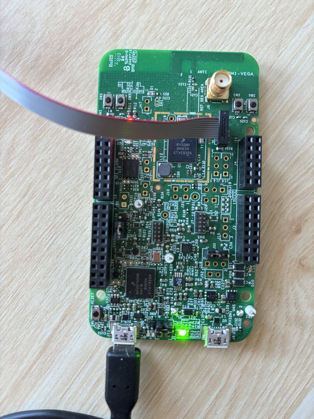
The OpenSDA USB port (J12) is a standard Micro-USB. Plugged into your laptop, it provides power to the board and also exposes LPUART0 (the pins we wired up in BOARD_InitDebugConsole) as a virtual serial device. On Linux (and inside our container) it usually enumerates as /dev/ttyACM0. This is the where you’ll see output from PRINTF() statements going to your terminal.
The RISC-V JTAG header (J55) is a small ribbon connector. The RV32M1 contains several CPU cores (RI5CY, ZERO-RISCY, and an ARM core) and this header is wired specifically to the JTAG chain of the RI5CY RISC-V core we care about. You can connect a SEGGER J-Link debugger here. Mind the ribbon cable orientation: the red stripe marks pin 1, and the right image above shows the correct direction. JTAG is the protocol every tool in the rest of this section uses to halt the CPU, program flash, set breakpoints, and single-step.
Note
Want to learn more about JTAG? See the Diving into JTAG series by Memfault.
The reset button (SW1) is a momentary push that pulls the chip’s reset line low. Pressing and releasing it re-runs the startup assembly from startup_RV32M1_ri5cy.S and re-enters main. Handy when a freshly-flashed image misbehaves, or when you just want a clean starting state without yanking the USB cable.
Flashing
“Flashing” means copying our built code into the non-volatile flash memory inside the RV32M1 so it persists across resets and power cycles. The binary data we send will travel out the J-Link over JTAG; for this, we use the Open On-Chip Debugger (OpenOCD) software (which translates JTAG data into higher-level “write this word to that address” operations) to talk to the chip’s on-board flash controller.
By hand
Flashing by hand looks like this:
openocd -f support/openocd/openocd_rv32m1_vega_ri5cy.cfg \
    -c "init" \
    -c "halt" \
    -c "ri5cy_boot" \
    -c "flash write_image erase build/blinky/blinky.elf" \
    -c "reset run" \
    -c "exit"
Each -c passes one TCL command to openocd after it finishes loading the config file:
initopens the JTAG connection and initializes openocd’s internal state.haltstops the CPU. We can’t reprogram the flash bank a program is currently executing from.ri5cy_bootis a vendor-supplied TCL routine defined in the config file. It selects the RI5CY core as the active target, since the chip exposes multiple cores on the same JTAG chain.flash write_image erase ...erases the sectors that will be written, then programs the ELF’s loadable segments into flash.reset runpulses reset and lets the CPU begin executing the newly-flashed image.exitdisconnects and shuts openocd down cleanly.
Note
If you are curious what
ri5cy_bootactually does, seesupport/openocd/openocd_rv32m1_vega_ri5cy.cfg. It essentially just pokes the chip’s control registers to bring the RI5CY core out of reset.
Using the Makefile
As always, the top-level Makefile provides a wrapper for easier use:
make flash-blinky
This first rebuilds the app if any source has changed, then hands the resulting ELF to openocd with the same command shown above. The command generalizes: make flash-<app> works for any app under apps/.
Debugging
Flashing gets code onto the board, but the moment something doesn’t work (wrong LED, hung in a loop, unexpected fault) you may need to inspect what the CPU is actually doing to get to the bottom of it. The same J-Link that programs flash can also act as a live window into the CPU’s state: we can halt the CPU at any address, read and write memory, inspect registers, and single-step through instructions.
The setup has two parts:
openocdruns as a GDB server, translating GDB’s remote serial protocol into JTAG operations. By convention, it listens on TCP port 3333.riscv32-unknown-elf-gdbruns as the client on your laptop. It loads the ELF’s debug information (source line numbers, variable names, struct layouts) and connects to theopenocdGDB server port.
Note
GDB stand for the The GNU Project Debugger, it’s a fairly standard tool worth learning more about!
Note that we need a RISC-V build of GDB (
riscv32-unknown-elf-gdb) since the target is a RISC-V core. This is included in the project’s container image for you.
By hand
In one terminal, start the server:
openocd -f support/openocd/openocd_rv32m1_vega_ri5cy.cfg \
    -c "init" -c "halt" -c "ri5cy_boot"
In a second terminal, launch GDB against the ELF and connect:
riscv32-unknown-elf-gdb build/blinky/blinky.elf \
    -ex "target remote :3333"
Using the Makefile
As with flashing, the Makefile provides shortcuts:
make gdbserver    # terminal 1
make gdb-blinky   # terminal 2
gdbserver runs openocd with exactly the three commands above. gdb-<app> launches GDB on the corresponding ELF and auto-connects to :3333.
A quick GDB cheat sheet
Once GDB is attached, here are some commands you’ll find useful:
monitor reset halt: reset the chip and stop at the first instructionbreak main(orb main): set a breakpoint atmaininfo breakpoints: show all breakpointsdelete <num>(d <num>): delete a breakpointcontinue(c): run until the next breakpoint or signalstep(s): advance one source line, descending into function callsnext(n): advance one source line, stepping over callsstepi(si): advance one machine instructionprint <expr>(p): evaluate a C expression.p *(GPIO_Type *)0x48020000dumps every field of the GPIOA register block/structinfo registers: show all CPU registersdisassemble <function>- show disassembly (machine code instructions) of functionload: reprogram flash through the debugger
Warning
Running
monitor reset haltwill leave OpenOCD and the RI5CY core out of sync. To reset cleanly from inside GDB, use the following sequence:(gdb) monitor reset halt (gdb) monitor ri5cy_boot (gdb) monitor halt (gdb) load (gdb) tbreak main (gdb) c
For blinky specifically, a quick sanity check is to b GPIO_TogglePinsOutput, continue, and confirm the breakpoint fires once per blink.
Viewing serial output
Debugging through GDB is great, but sometimes using print statements over UART is just less hassle. Anything the board writes over LPUART0 comes back on the OpenSDA USB (J12).
Note
We’ll learn more about UART in Communicating with the world.
The Makefile provides a helper for this:
make serial
This opens minicom at 115200 baud (matching the rate BOARD_InitDebugConsole configured) against the first /dev/ttyACM*, /dev/ttyUSB*, or /dev/cu.usbmodem* it finds. After flashing blinky you should see the RV32M1-VEGA RI5CY baremetal app banner and then Starting to blink LED....
TLDR
- You need to know about 2 connections and a button: OpenSDA USB (J12) for power and serial, RISC-V JTAG (J55) for flashing and debugging, and reset (SW1) to restart the chip.
- Flashing uses
openocdto write our program into the chip’s flash.- You can use
make flash-<app>to flash any app.
- You can use
- Debugging is a two-process setup:
openocdas a GDB server on port 3333, andriscv32-unknown-elf-gdbas the client.- You can use
make gdbserverin one terminal plusmake gdb-<app>in another.
- You can use
make serialopens the virtual UART at 115200 baud, which is where everyPRINTFin your application ends up.